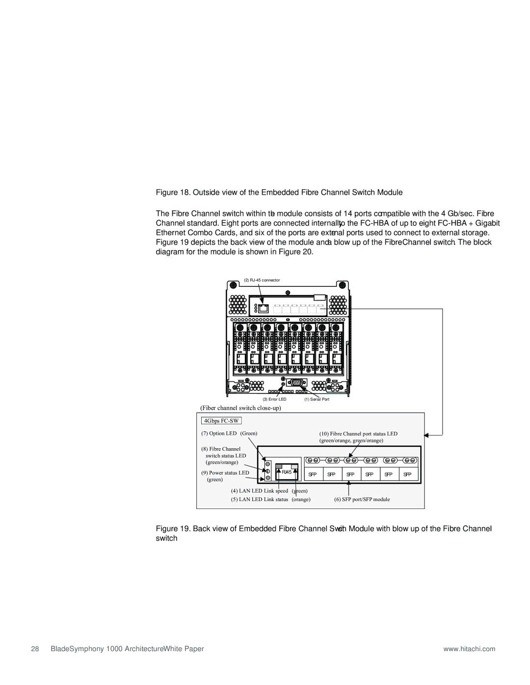
Figure 18. Outside view of the Embedded Fibre Channel Switch Module
The Fibre Channel switch within the module consists of 14 ports compatible with the 4 Gb/sec. Fibre Channel standard. Eight ports are connected internally to the FC-HBA of up to eight FC-HBA + Gigabit Ethernet Combo Cards, and six of the ports are external ports used to connect to external storage. Figure 19 depicts the back view of the module and a blow up of the Fibre Channel switch. The block diagram for the module is shown in Figure 20.
(2) |
|
| (3) Error LED | (1) Serial Port |
(Fiber channel switch |
| ||
|
|
|
|
| 4Gbps |
|
|
| (7) Option LED (Green) | (10) Fibre Channel port status LED | |
|
|
| (green/orange, green/orange) |
(8)Fibre Channel switch status LED
(green/orange)
(9) Power status LED ![]() (green)
(green) ![]()
![]()
RJ45 |
SFP
SFP SFP SFP SFP
SFP
(4) LAN LED Link speed (green)
(5) LAN LED Link status (orange) | (6) SFP port/SFP module |
Figure 19. Back view of Embedded Fibre Channel Switch Module with blow up of the Fibre Channel switch
28 BladeSymphony 1000 Architecture White Paper | www.hitachi.com |
