Port 1
Port 2
Port3
Port4
Redun
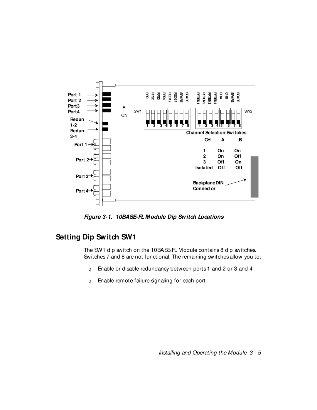
RFS1 | RFS2 | RFS3 | RFS4 | RED12 | RED34 | SPARE | SPARE | PRTEN1 | PRTEN2 | PRTEN3 | PRTEN4 | CHA |
|
|
|
|
|
|
|
|
|
|
|
|
|
ON
1 | 2 | 3 | 4 | 5 | 6 | 7 | 8 | 1 | 2 | 3 | 4 | 5 |
CHB | SPARE | SPARE |
SW2
6 7 8
Port 1 |
Port 2 |
Port 3 |
Port 4![]()
![]()
![]()
Channel Selection Switches
CH | A | B |
1 | On | On |
2 | On | Off |
3 | Off | On |
Isolated | Off | Off |
BackplaneDIN ![]() Connector
Connector
Figure 3-1. 10BASE-FL Module Dip Switch Locations
Setting Dip Switch SW1
The SW1 dip switch on the
❑Enable or disable redundancy between ports 1 and 2 or 3 and 4
❑Enable remote failure signaling for each port
Installing and Operating the Module 3 - 5