Verifying the LED and Network Assignments
Once you install the module, verify its operation through the front panel of the ONline Controller Module. The Controller Module is equipped with an LED check button on the front panel. Use the LED check button to:
❑Verify LED operation
❑Verify network (channel) assignment
When you press this button, the Controller Module initiates a test to all modules in the concentrator. All LEDs should respond by lighting continuously for approximately five seconds. Any LED that does not light is defective.
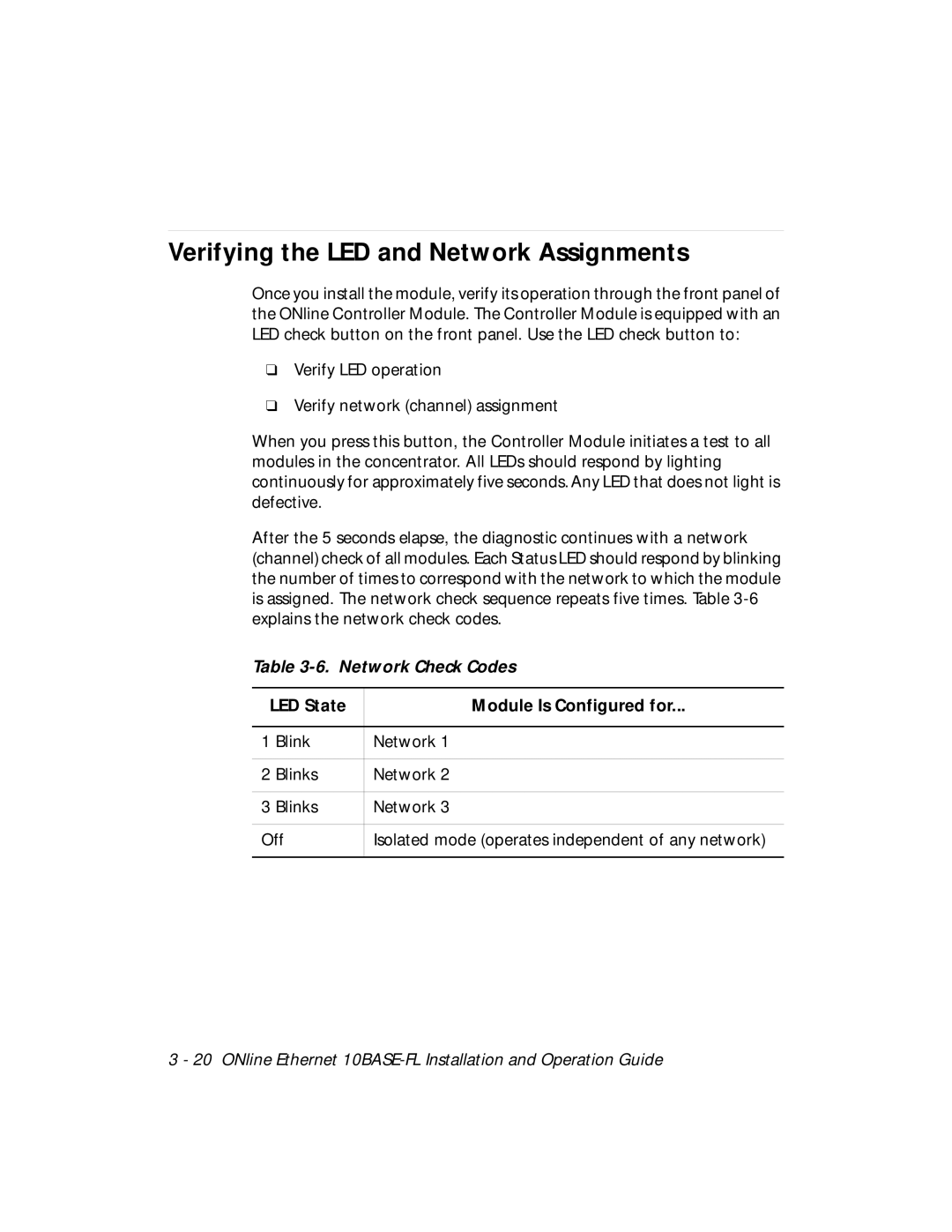
After the 5 seconds elapse, the diagnostic continues with a network (channel) check of all modules. Each Status LED should respond by blinking the number of times to correspond with the network to which the module is assigned. The network check sequence repeats five times. Table
Table 3-6. Network Check Codes
LED State | Module Is Configured for... | |
|
|
|
1 | Blink | Network 1 |
|
|
|
2 | Blinks | Network 2 |
|
|
|
3 | Blinks | Network 3 |
|
| |
Off | Isolated mode (operates independent of any network) | |
|
|
|