Texas Instruments TMS320DM648 manual Video Capture Fifo Configurations

Models: TMS320DM648

1 174
Download 174 pages 10.69 Kb
Page 20
Image 20

www.ti.com

Video Port FIFO

1.2.2 Video Capture FIFO Configurations

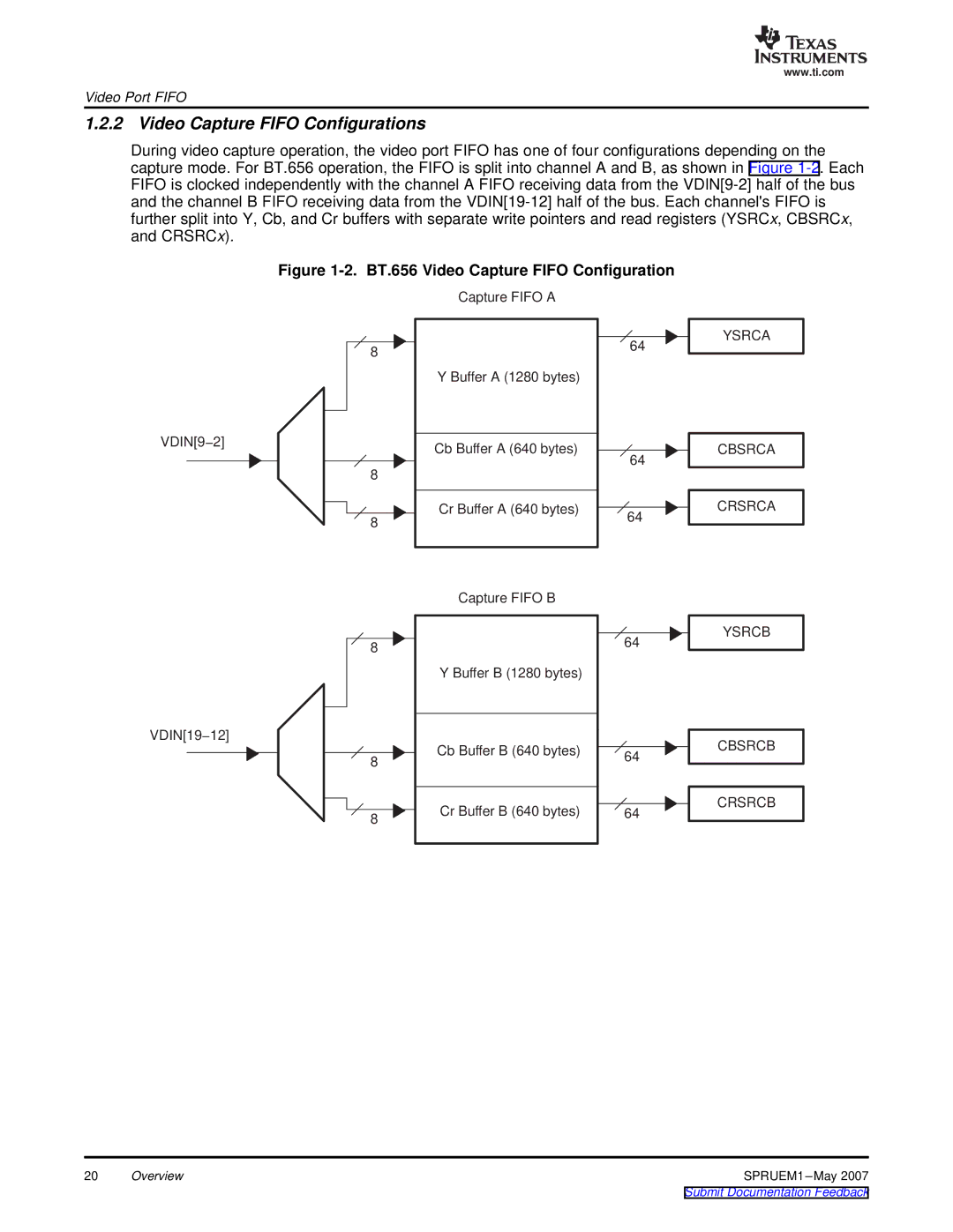
During video capture operation, the video port FIFO has one of four configurations depending on the capture mode. For BT.656 operation, the FIFO is split into channel A and B, as shown in Figure 1-2. Each FIFO is clocked independently with the channel A FIFO receiving data from the VDIN[9-2] half of the bus and the channel B FIFO receiving data from the VDIN[19-12] half of the bus. Each channel'sFIFO is further split into Y, Cb, and Cr buffers with separate write pointers and read registers (YSRCx, CBSRCx, and CRSRCx).

Figure 1-2. BT.656 Video Capture FIFO Configuration

VDIN[9−2]

8

8

8

Capture FIFO A

Y Buffer A (1280 bytes)

Cb Buffer A (640 bytes)

Cr Buffer A (640 bytes)

64

64

64

YSRCA

CBSRCA

CRSRCA

VDIN[19−12]

8

8

8

Capture FIFO B

Y Buffer B (1280 bytes)

Cb Buffer B (640 bytes)

Cr Buffer B (640 bytes)

64

64

64

YSRCB

CBSRCB

CRSRCB

20

Overview

SPRUEM1 –May 2007

Submit Documentation Feedback

Page 20
Image 20
Texas Instruments TMS320DM648 manual Video Capture Fifo Configurations, BT.656 Video Capture Fifo Configuration