www.ti.com
Video Port Control Registers
2.3.4 EDMA Interface Operation
When the video port is configured for capture (or TCI) mode, it only accepts read requests from the EDMA interface. Write requests are false acknowledged (so the bus does not stall) and the data is discarded. When the video port is configured for display mode, it only accepts write requests. Read requests are false acknowledged (so the bus does not stall) and an arbitrary data value is returned.
When the video port is in reset, is not enabled (PEREN bit cleared), halted (VPHALT bit is set), or the active mode is not enabled (VCEN or VDEN bit is cleared), then the port will false acknowledge all EDMA accesses to prevent bus lockup.
The video port EDMA event generation logic is very tightly coupled to the EDMA interface accesses. An incorrectly programmed EDMA size causes the EDMA and FIFO to become misaligned causing aberrations in the captured or displayed data and likely resulting in an eventual FIFO overflow or underflow. In the same manner, if another system EDMA incorrectly addresses the video port during active capture or display, the video port has no way of determining that this is an errant EDMA because all it monitors is a EDMA access so it must perform the FIFO read or write. Such an errant EDMA eventually causes the FIFO to be
2.4Video Port Control Registers
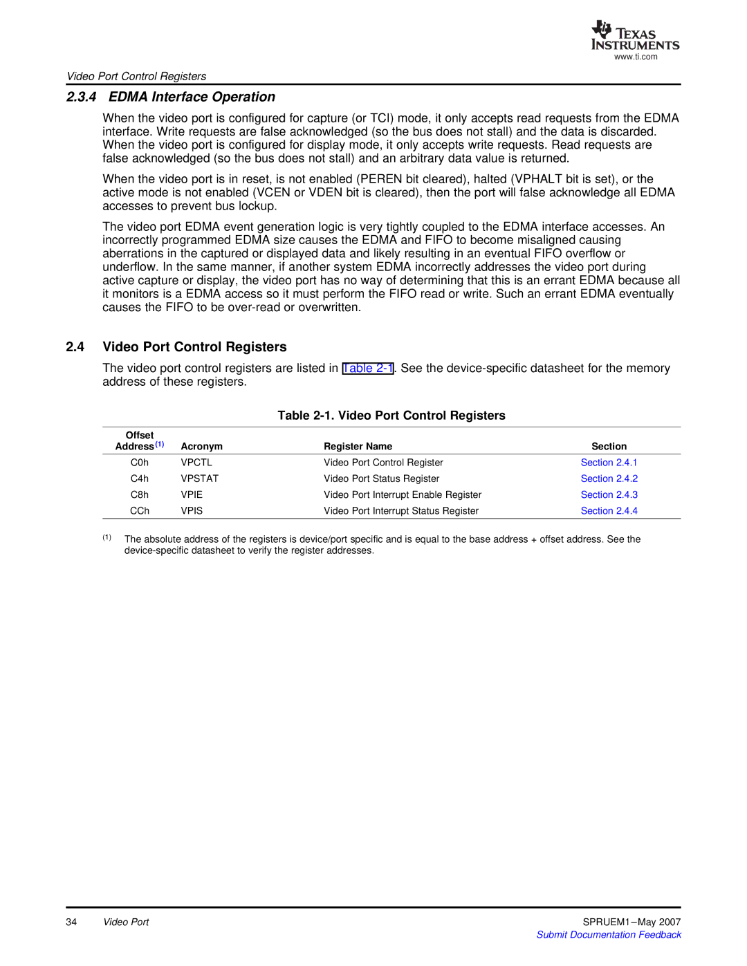
The video port control registers are listed in Table
Table 2-1. Video Port Control Registers
Offset |
|
|
|
Address (1) | Acronym | Register Name | Section |
C0h | VPCTL | Video Port Control Register | Section 2.4.1 |
C4h | VPSTAT | Video Port Status Register | Section 2.4.2 |
C8h | VPIE | Video Port Interrupt Enable Register | Section 2.4.3 |
CCh | VPIS | Video Port Interrupt Status Register | Section 2.4.4 |
(1)The absolute address of the registers is device/port specific and is equal to the base address + offset address. See the
34 | Video Port | SPRUEM1 |
|
| Submit Documentation Feedback |
