www.ti.com
BT.656 and Y/C Mode Field and Frame Operation
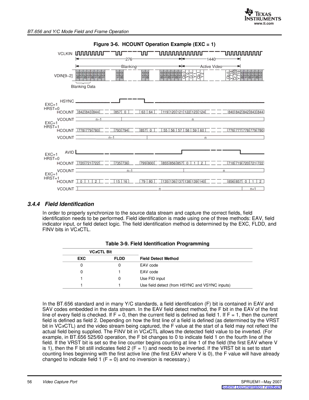
Figure 3-6. HCOUNT Operation Example (EXC = 1)
VCLKIN
276 | 1440 |
Blanking | Active Video |
VDIN[9−2] | 80.0 10.0 80.0 10.0 80.0 10.0 80.0 10.0 | 10.0 | 80.0 | 10.0 | 80.0 | 80.0 | 10.0 | 80.0 | 10.0 | 80.0 | 10.0 Cb0 | Y0 | Cr0 | Y1 | Cb1 | Y2 | Cb0 | Y718 | Cr359 | Y719 |
|
|
|
|
|
|
|
|
|
|
|
|
|
|
|
|
|
|
|
|
80.0 | 10.0 | 80.0 | 10.0 | 80.0 | 10.0 |
Blanking Data
HSYNC
EXC=1 |
|
|
|
|
|
|
|
|
|
|
|
|
|
|
|
|
|
|
|
|
|
|
|
|
HRST=0 |
|
|
|
|
|
|
|
|
|
|
|
|
|
|
|
|
|
|
|
|
|
|
|
|
HCOUNT |
| 842 | 843 | 844 |
|
| 857 | 0 |
| 63 | 64 |
| 119 | 120 | 121 | 122 | 123 | 124 |
| 840 | 842 | 842 | 843 | 844 |
VCOUNT |
|
|
|
|
|
|
|
|
|
|
|
|
|
|
|
|
|
|
|
|
|
|
|
|
|
|
| n−1 |
|
|
|
|
|
|
|
|
|
|
| n |
|
|
|
|
|
|
| ||
EXC=1 |
|
|
|
|
|
|
|
|
|
|
|
|
|
|
|
|
|
|
|
|
|
|
|
|
HRST=1 |
|
|
|
|
|
|
|
|
|
|
|
|
|
|
|
|
|
|
|
|
|
|
|
|
HCOUNT |
| 778 | 779 | 780 |
|
| 793 | 794 |
| 857 | 0 |
| 55 | 56 | 57 | 58 | 59 | 60 |
| 776 | 777 | 778 | 779 | 780 |
VCOUNT |
|
|
|
|
| n−1 |
|
|
|
|
|
|
|
|
|
|
|
|
|
|
|
|
| |
|
|
|
|
|
|
|
|
|
|
|
|
|
|
| n |
|
|
|
|
| ||||
EXC=1 AVID HRST=0
HCOUNT
VCOUNT EXC=1
HRST=1
HCOUNT
VCOUNT
| 720 | 721 | 722 |
| 735 | 736 |
| 799 | 800 |
| 855 | 856 | 857 | 0 | 1 | 2 |
| 718 | 719 | 720 | 721 | 722 |
|
|
|
|
|
|
|
|
|
|
|
|
|
|
|
|
|
|
|
|
|
|
|
|
|
|
|
|
| n−1 |
|
|
|
|
|
|
|
|
| n |
|
|
| |||
|
|
|
|
|
|
|
|
|
|
|
|
|
|
|
|
|
|
|
|
|
|
|
| 0 | 1 | 2 |
| 15 | 16 |
| 79 | 80 |
| 135 | 136 | 137 | 138 | 139 | 140 |
| 856 | 857 | 0 | 1 | 2 |
|
|
|
|
|
|
|
|
|
|
|
|
|
|
|
|
|
|
|
| |||
|
|
|
|
|
|
|
|
|
| n |
|
|
|
|
|
|
| n+1 |
| |||
3.4.4 Field Identification
In order to properly synchronize to the source data stream and capture the correct fields, field identification needs to be performed. Field identification is made using one of three methods: EAV, field indicator input, or field detect logic. The field identification method is determined by the EXC, FLDD, and FINV bits in VCxCTL.
Table 3-9. Field Identification Programming
| VCxCTL Bit |
|
EXC | FLDD | Field Detect Method |
0 | 0 | EAV code |
0 | 1 | EAV code |
1 | 0 | Use FID input |
1 | 1 | Use field detect (from HSYNC and VSYNC inputs) |
In the BT.656 standard and in many Y/C standards, a field identification (F) bit is contained in EAV and SAV codes embedded in the data stream. In the EAV field detect method, the F bit in the EAV of the first line of every field is checked. If F = 0, then the current field is defined as field 1. If F = 1, then the current field is defined as field 2. Depending on how the first line of a field is defined (as determined by the VRST bit in VCxCTL) and the video stream being captured, the F value at the start of a field may not reflect the actual field being supplied. The FINV bit in VCxCTL allows the detected field value to be inverted. (For example, in BT.656 525/60 operation, the F bit changes to 0 to indicate field 1 on the fourth line of the field. If the VRST bit is set so the line counter begins counting at line 1 of the field (the first EAV where V is 1), then the F bit still indicates field 2 (F = 1) and needs to be inverted. If the VRST bit is set to start counting lines beginning with the first active line (the first EAV where V is 0), the F value will have already changed to indicate field 1 (F = 0) and no inversion is necessary.)
56 | Video Capture Port | SPRUEM1 |