www.ti.com
Capture Line Boundary Conditions
The video port generates a YEVT after the specified number of new samples has been captured in the buffer. The number of samples required to generate YEVT is programmable and is set in the VCTHRLD1 bits of VCATHRLD. VCTHRLD1 should be set to the packet size plus 8 bytes of timestamp. On every YEVT, the EDMA should move data from the buffer to the DSP memory. When moving data from the buffer to the DSP memory, the EDMA should use the memory address of the YSRCA location as a source address.
3.9Capture Line Boundary Conditions
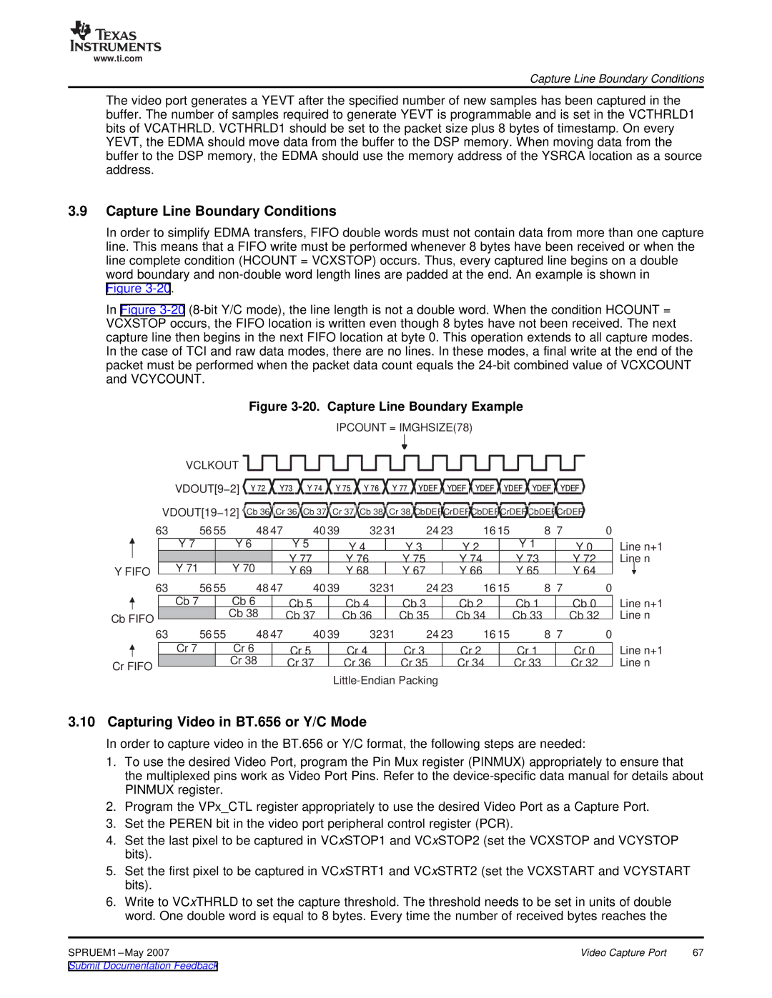
In order to simplify EDMA transfers, FIFO double words must not contain data from more than one capture line. This means that a FIFO write must be performed whenever 8 bytes have been received or when the line complete condition (HCOUNT = VCXSTOP) occurs. Thus, every captured line begins on a double word boundary and
Figure
In Figure
Figure 3-20. Capture Line Boundary Example
IPCOUNT = IMGHSIZE(78)
VCLKOUT
|
|
| VDOUT[9−2] | Y 72 | Y73 | Y 74 |
|
| Y | 75 | Y 76 |
|
| Y | 77 YDEF YDEF YDEF YDEF YDEF YDEF | |||||||||||||||||||||||||
|
|
|
|
|
|
|
|
|
|
|
|
|
|
|
|
|
|
|
|
|
|
|
|
|
|
|
|
|
|
| ||||||||||
|
| VDOUT[19−12] Cb 36 | Cr 36 | Cb 37 |
|
| Cr 37 |
| Cb 38 |
|
| Cr 38 CbDEFCrDEFCbDEFCrDEF CbDEFCrDEF | ||||||||||||||||||||||||||||
63 | 56 55 |
| 48 47 |
|
| 40 39 |
|
| 32 31 | 24 23 | 16 15 | 8 7 | 0 | |||||||||||||||||||||||||||
|
|
| Y 7 |
| Y 6 |
|
| Y 5 |
|
|
| Y 4 |
|
|
| Y 3 |
| Y 2 |
| Y 1 |
|
| Y 0 | |||||||||||||||||
|
|
|
|
|
|
|
|
|
| Y 77 |
|
|
| Y 76 |
|
|
| Y 75 |
| Y 74 |
| Y 73 |
| Y 72 | ||||||||||||||||
|
|
|
|
|
|
|
|
|
|
|
|
|
|
|
| |||||||||||||||||||||||||
Y FIFO |
| Y 71 |
| Y 70 |
|
| Y 69 |
|
|
| Y 68 |
|
|
| Y 67 |
| Y 66 |
| Y 65 |
| Y 64 | |||||||||||||||||||
|
|
|
|
|
|
|
|
|
|
|
|
|
|
|
|
|
|
|
|
| ||||||||||||||||||||
63 | 56 55 |
| 48 47 |
|
| 40 39 |
|
| 3231 | 24 23 | 16 15 | 8 7 | 0 | |||||||||||||||||||||||||||
|
|
| Cb 7 |
| Cb 6 |
|
| Cb 5 |
|
|
| Cb 4 |
|
|
| Cb 3 |
| Cb 2 |
| Cb 1 |
| Cb 0 | ||||||||||||||||||
Cb FIFO |
|
|
| Cb 38 |
|
| Cb 37 |
|
|
| Cb 36 |
|
|
| Cb 35 |
| Cb 34 |
| Cb 33 |
| Cb 32 | |||||||||||||||||||
|
|
|
|
|
|
|
|
|
|
|
|
|
|
|
|
|
|
|
|
|
|
|
|
|
|
|
|
|
|
|
|
|
|
|
|
|
|
| ||
63 | 56 55 |
| 48 47 |
|
| 40 39 |
|
| 3231 | 24 23 | 16 15 | 8 7 | 0 | |||||||||||||||||||||||||||
|
|
|
|
|
|
|
|
|
|
|
|
|
|
|
|
|
|
|
| |||||||||||||||||||||
|
|
| Cr 7 |
| Cr 6 |
|
| Cr 5 |
|
|
| Cr 4 |
|
|
| Cr 3 |
| Cr 2 |
| Cr 1 |
| Cr 0 | ||||||||||||||||||
Cr FIFO |
|
|
| Cr 38 |
|
| Cr 37 |
|
|
| Cr 36 |
|
|
| Cr 35 |
| Cr 34 |
| Cr 33 |
| Cr 32 | |||||||||||||||||||
|
|
|
|
|
|
|
|
|
|
|
|
|
|
|
|
|
|
|
|
|
|
|
|
|
| |||||||||||||||
|
|
|
|
|
|
|
|
|
|
|
|
|
|
|
|
|
|
|
|
|
|
|
|
|
|
|
| |||||||||||||
Line n+1 Line n
Line n+1 Line n
Line n+1 Line n
3.10 Capturing Video in BT.656 or Y/C Mode
In order to capture video in the BT.656 or Y/C format, the following steps are needed:
1.To use the desired Video Port, program the Pin Mux register (PINMUX) appropriately to ensure that the multiplexed pins work as Video Port Pins. Refer to the
2.Program the VPx_CTL register appropriately to use the desired Video Port as a Capture Port.
3.Set the PEREN bit in the video port peripheral control register (PCR).
4.Set the last pixel to be captured in VCxSTOP1 and VCxSTOP2 (set the VCXSTOP and VCYSTOP bits).
5.Set the first pixel to be captured in VCxSTRT1 and VCxSTRT2 (set the VCXSTART and VCYSTART bits).
6.Write to VCxTHRLD to set the capture threshold. The threshold needs to be set in units of double word. One double word is equal to 8 bytes. Every time the number of received bytes reaches the
SPRUEM1 | Video Capture Port | 67 |