www.ti.com
|
|
| Video Capture Registers |
| Table |
| |
Offset |
|
|
|
Address (1) | Acronym | Register Name | Section |
154h | VCBSTOP2 | Video Capture Channel B Field 2 Stop Register | Section 3.13.6 |
158h | VCBVINT | Video Capture Channel B Vertical Interrupt Register | Section 3.13.7 |
15Ch | VCBTHRLD | Video Capture Channel B Threshold Register | Section 3.13.8 |
160h | VCBEVTCT | Video Capture Channel B Event Count Register | Section 3.13.9 |
180h | TCICTL | TCI Capture Control Register | Section 3.13.11 |
184h | TCICLKINITL | TCI Clock Initialization LSB Register | Section 3.13.12 |
188h | TCICLKINITM | TCI Clock Initialization MSB Register | Section 3.13.13 |
18Ch | TCISTCLKL | TCI System Time Clock LSB Register | Section 3.13.14 |
190h | TCISTCLKM | TCI System Time Clock MSB Register | Section 3.13.15 |
194h | TCISTCMPL | TCI System Time Clock Compare LSB Register | Section 3.13.16 |
198h | TCISTCMPM | TCI System Time Clock Compare MSB Register | Section 3.13.17 |
19Ch | TCISTMSKL | TCI System Time Clock Compare Mask LSB Register | Section 3.13.18 |
1A0h | TCISTMSKM | TCI System Time Clock Compare Mask MSB Register | Section 3.13.19 |
1A4h | TCITICKS | TCI System Time Clock Ticks Interrupt Register | Section 3.13.20 |
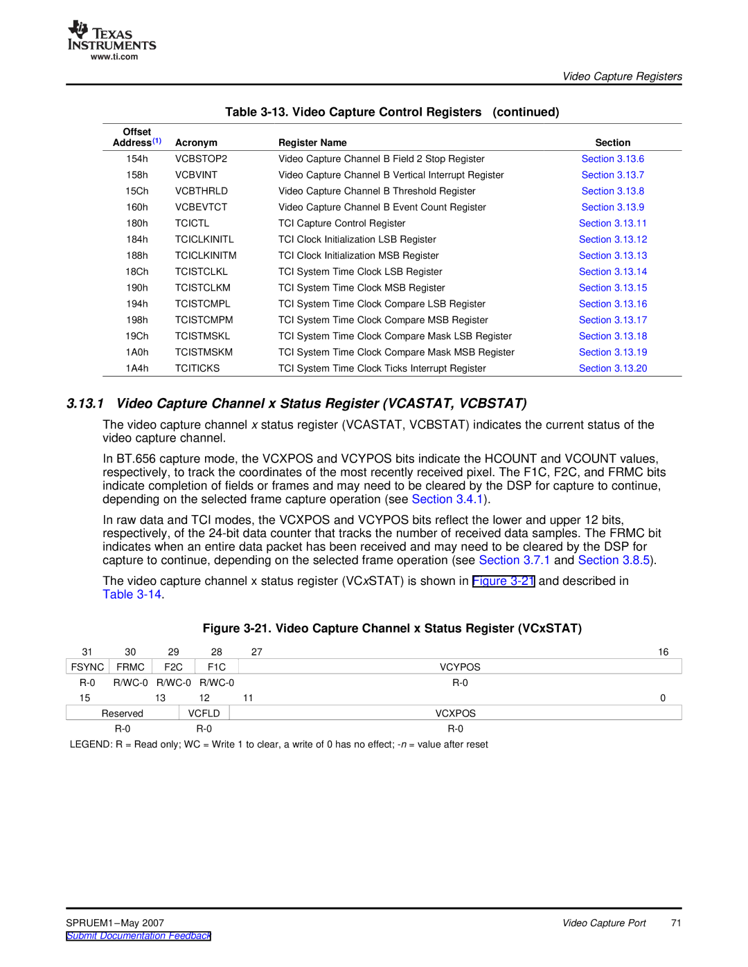
3.13.1 Video Capture Channel x Status Register (VCASTAT, VCBSTAT)
The video capture channel x status register (VCASTAT, VCBSTAT) indicates the current status of the video capture channel.
In BT.656 capture mode, the VCXPOS and VCYPOS bits indicate the HCOUNT and VCOUNT values, respectively, to track the coordinates of the most recently received pixel. The F1C, F2C, and FRMC bits indicate completion of fields or frames and may need to be cleared by the DSP for capture to continue, depending on the selected frame capture operation (see Section 3.4.1).
In raw data and TCI modes, the VCXPOS and VCYPOS bits reflect the lower and upper 12 bits, respectively, of the
The video capture channel x status register (VCxSTAT) is shown in Figure
Figure 3-21. Video Capture Channel x Status Register (VCxSTAT)
31 | 30 | 29 | 28 | 27 | 16 |
FSYNC | FRMC | F2C | F1C |
| VCYPOS |
| |||||
15 |
| 13 | 12 | 11 | 0 |
Reserved |
| VCFLD |
| VCXPOS | |
|
|
| |||
LEGEND: R = Read only; WC = Write 1 to clear, a write of 0 has no effect;
SPRUEM1 | Video Capture Port | 71 |
Submit Documentation Feedback |
|
|