www.ti.com
TCI Capture Mode
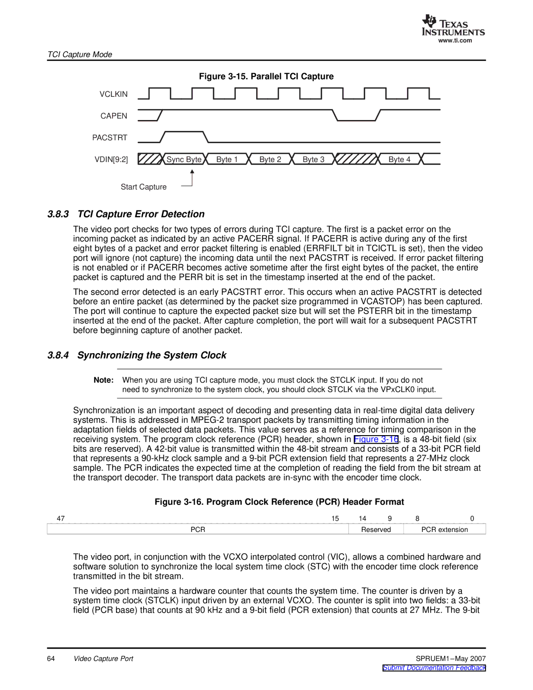
Figure 3-15. Parallel TCI Capture
VCLKIN |
|
|
|
|
CAPEN |
|
|
|
|
PACSTRT |
|
|
|
|
VDIN[9:2] | Sync Byte Byte 1 | Byte 2 | Byte 3 | Byte 4 |
Start Capture |
|
|
|
|
3.8.3 TCI Capture Error Detection
The video port checks for two types of errors during TCI capture. The first is a packet error on the incoming packet as indicated by an active PACERR signal. If PACERR is active during any of the first eight bytes of a packet and error packet filtering is enabled (ERRFILT bit in TCICTL is set), then the video port will ignore (not capture) the incoming data until the next PACSTRT is received. If error packet filtering is not enabled or if PACERR becomes active sometime after the first eight bytes of the packet, the entire packet is captured and the PERR bit is set in the timestamp inserted at the end of the packet.
The second error detected is an early PACSTRT error. This occurs when an active PACSTRT is detected before an entire packet (as determined by the packet size programmed in VCASTOP) has been captured. The port will continue to capture the expected packet size but will set the PSTERR bit in the timestamp inserted at the end of the packet. After capture completion, the port will wait for a subsequent PACSTRT before beginning capture of another packet.
3.8.4 Synchronizing the System Clock
Note: When you are using TCI capture mode, you must clock the STCLK input. If you do not need to synchronize to the system clock, you should clock STCLK via the VPxCLK0 input.
Synchronization is an important aspect of decoding and presenting data in
Figure 3-16. Program Clock Reference (PCR) Header Format
47 | 15 | 14 | 9 | 8 | 0 |
PCR |
| Reserved |
| PCR extension | |
The video port, in conjunction with the VCXO interpolated control (VIC), allows a combined hardware and software solution to synchronize the local system time clock (STC) with the encoder time clock reference transmitted in the bit stream.
The video port maintains a hardware counter that counts the system time. The counter is driven by a system time clock (STCLK) input driven by an external VCXO. The counter is split into two fields: a
64 | Video Capture Port | SPRUEM1 |