www.ti.com
Video Capture Registers
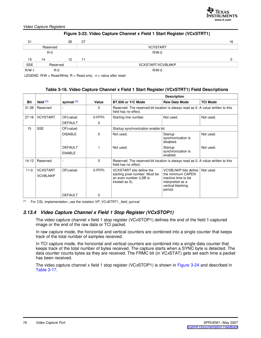
Figure 3-23. Video Capture Channel x Field 1 Start Register (VCxSTRT1)
31 |
| 28 | 27 | 16 |
| Reserved |
|
| VCYSTART |
|
|
| ||
15 | 14 | 12 | 11 | 0 |
SSE | Reserved |
|
| VCXSTART/VCVBLNKP |
|
|
LEGEND: R/W = Read/Write; R = Read only;
Table
|
|
|
|
| Description |
|
Bit | field (1) | symval (1) | Value | BT.656 or Y/C Mode | Raw Data Mode | TCI Mode |
Reserved | - | 0 | Reserved. The reserved bit location is always read as 0. A value written to this | |||
|
|
|
| field has no effect. |
|
|
VCYSTART | OF(value) | Starting line number. | Not used. | Not used. | ||
|
| DEFAULT | 0 |
|
|
|
15 | SSE | OF(value) |
| Startup synchronization enable bit. |
| |
|
| DISABLE | 0 | Not used. | Startup | Not used. |
|
|
|
|
| synchronization is |
|
|
|
|
|
| disabled. |
|
|
| DEFAULT | 1 | Not used. | Startup | Not used. |
|
| ENABLE |
|
| synchronization is |
|
|
|
|
| enabled. |
| |
|
|
|
|
|
| |
Reserved | - | 0 | Reserved. The reserved bit location is always read as 0. A value written to this | |||
|
|
|
| field has no effect. |
|
|
VCXSTART | OF(value) | VCXSTART bits define the | VCVBLNKP bits define | Not used. | ||
| VCVBLNKP |
|
| starting pixel number. Must be | the minimum CAPEN |
|
|
|
| an even number (LSB is | inactive time to be |
| |
|
|
|
|
| ||
|
|
|
| treated as 0). | interpreted as a |
|
|
|
|
|
| vertical blanking |
|
|
|
|
|
| period. |
|
|
| DEFAULT | 0 |
|
|
|
(1)For CSL implementation, use the notation VP_VCxSTRT1_field_symval
3.13.4 Video Capture Channel x Field 1 Stop Register (VCxSTOP1)
The video capture channel x field 1 stop register (VCxSTOP1) defines the end of the field
In raw capture mode, the horizontal and vertical counters are combined into a single counter that keeps track of the total number of samples received.
In TCI capture mode, the horizontal and vertical counters are combined into a single data counter that keeps track of the total number of bytes received. The capture starts when a SYNC byte is detected. The data counter counts bytes as they are received. The FRMC bit (in VCxSTAT) gets set each time a packet has been received.
The video capture channel x field 1 stop register (VCxSTOP1) is shown in Figure
76 | Video Capture Port | SPRUEM1 |