www.ti.com
Video Display Registers
4.12.22 Video Display Event Register (VDDISPEVT)
The video display event register (VDDISPEVT) is programmed with the number of EDMA events to be generated for display field 1 and field 2.
The video display event register (VDDISPEVET) is shown in Figure
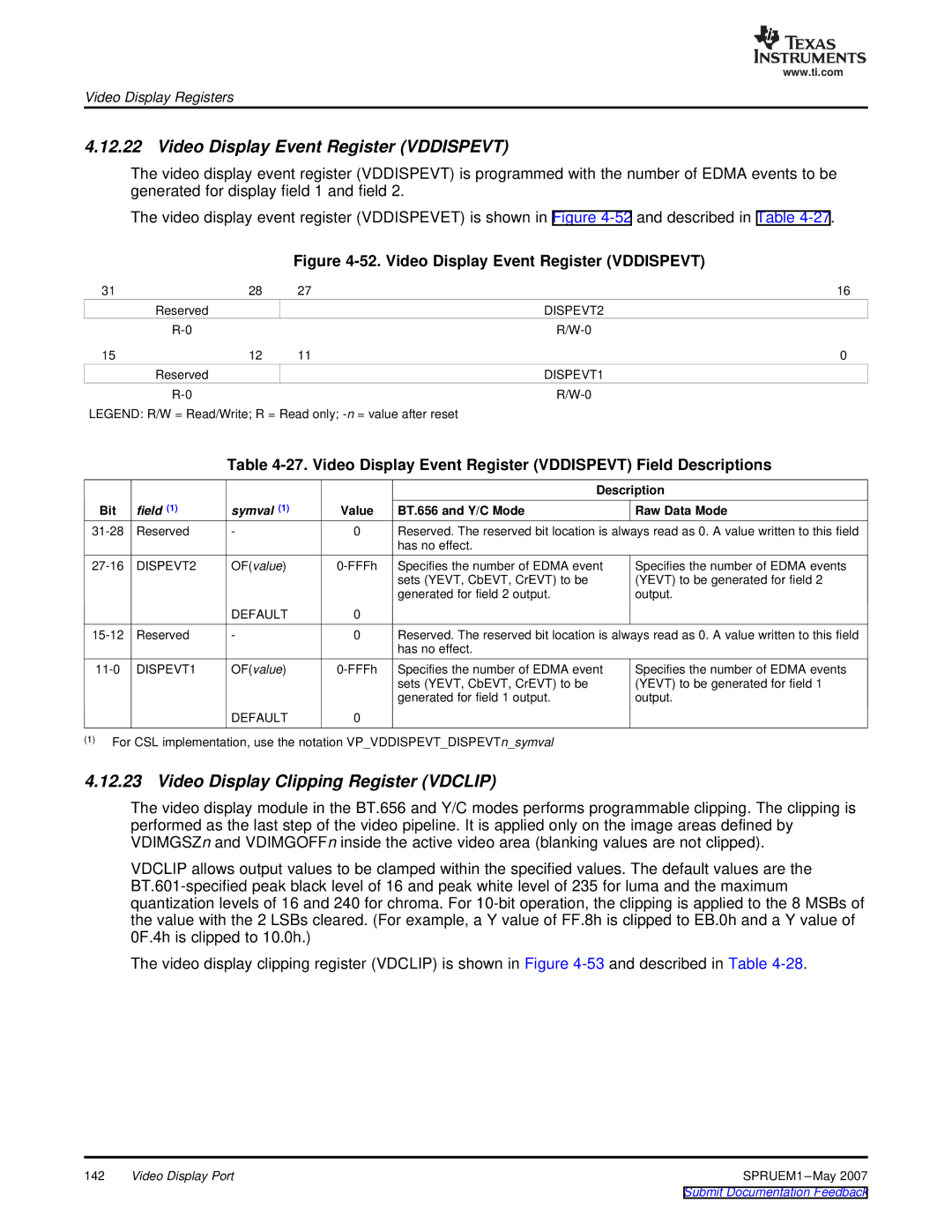
Figure 4-52. Video Display Event Register (VDDISPEVT)
31 | 28 | 27 | 16 |
| Reserved |
| DISPEVT2 |
|
| ||
15 | 12 | 11 | 0 |
| Reserved |
| DISPEVT1 |
|
|
LEGEND: R/W = Read/Write; R = Read only;
Table
|
|
|
|
| Description |
Bit | field (1) | symval (1) | Value | BT.656 and Y/C Mode | Raw Data Mode |
Reserved | - | 0 | Reserved. The reserved bit location is always read as 0. A value written to this field | ||
|
|
|
| has no effect. |
|
OF(value) | ||
|
| sets (YEVT, CbEVT, CrEVT) to be |
|
| generated for field 2 output. |
| DEFAULT | 0 |
Specifies the number of EDMA events (YEVT) to be generated for field 2 output.
- | 0 | Reserved. The reserved bit location is always read as 0. A value written to this field | |
|
|
| has no effect. |
OF(value) | ||
|
| sets (YEVT, CbEVT, CrEVT) to be |
|
| generated for field 1 output. |
| DEFAULT | 0 |
Specifies the number of EDMA events (YEVT) to be generated for field 1 output.
(1)For CSL implementation, use the notation VP_VDDISPEVT_DISPEVTn_symval
4.12.23 Video Display Clipping Register (VDCLIP)
The video display module in the BT.656 and Y/C modes performs programmable clipping. The clipping is performed as the last step of the video pipeline. It is applied only on the image areas defined by VDIMGSZn and VDIMGOFFn inside the active video area (blanking values are not clipped).
VDCLIP allows output values to be clamped within the specified values. The default values are the
The video display clipping register (VDCLIP) is shown in Figure
142 | Video Display Port | SPRUEM1 |