www.ti.com
Video Display Registers
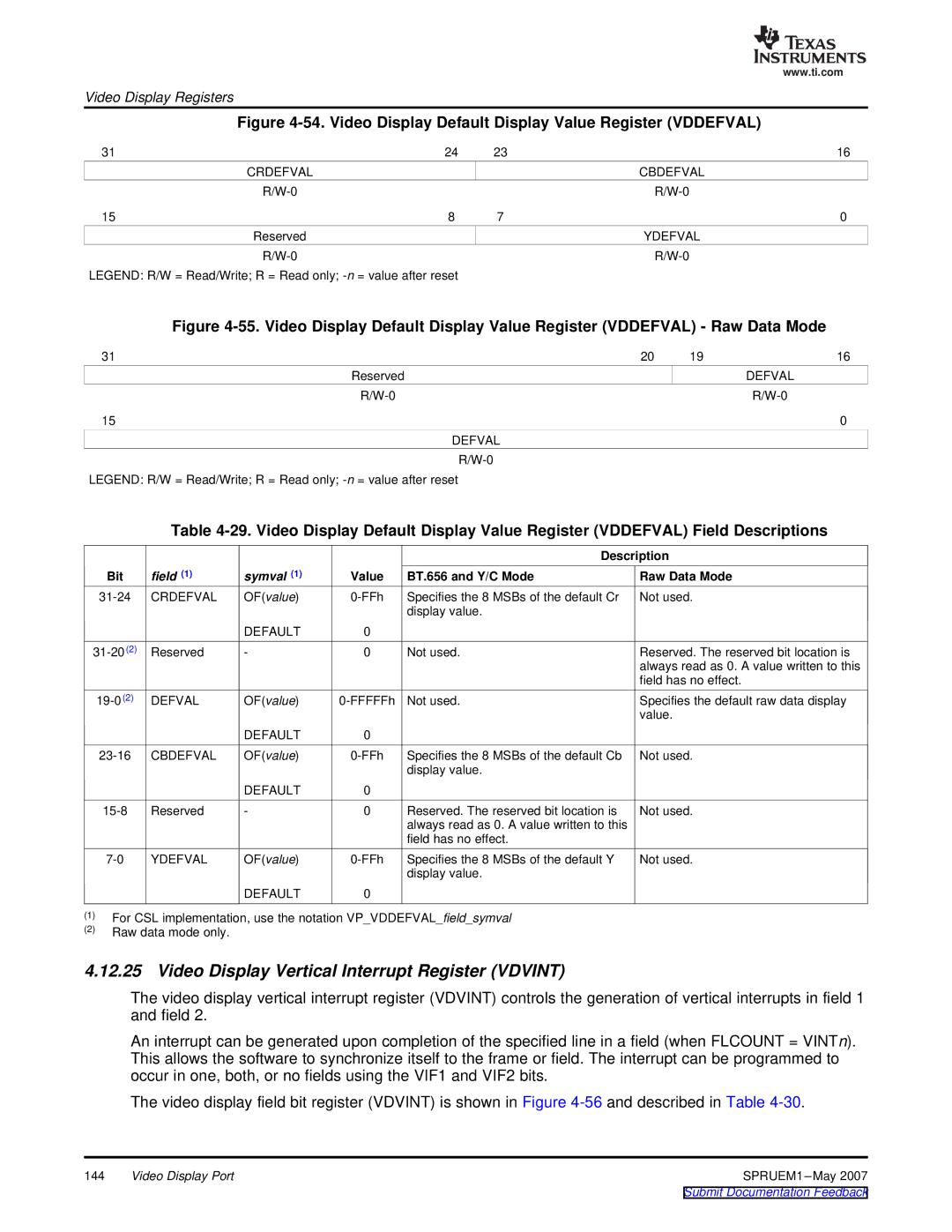
Figure 4-54. Video Display Default Display Value Register (VDDEFVAL)
31 | 24 | 23 | 16 |
| CRDEFVAL |
| CBDEFVAL |
|
| ||
15 | 8 | 7 | 0 |
| Reserved |
| YDEFVAL |
|
|
LEGEND: R/W = Read/Write; R = Read only;
Figure 4-55. Video Display Default Display Value Register (VDDEFVAL) - Raw Data Mode
31 | 20 | 19 | 16 |
Reserved |
|
| DEFVAL |
|
| ||
15 |
|
| 0 |
DEFVAL
LEGEND: R/W = Read/Write; R = Read only;
Table
|
|
|
| Description |
Bit | field (1) | symval (1) | Value BT.656 and Y/C Mode | Raw Data Mode |
CRDEFVAL | OF(value) | Specifies the 8 MSBs of the default Cr | ||
|
|
|
| display value. |
|
| DEFAULT | 0 |
|
Reserved | - | 0 | Not used. |
Not used.
Reserved. The reserved bit location is always read as 0. A value written to this field has no effect.
DEFVAL | OF(value) | Not used. | Specifies the default raw data display | ||
|
|
|
|
| value. |
|
| DEFAULT | 0 |
|
|
CBDEFVAL | OF(value) | Specifies the 8 MSBs of the default Cb | Not used. | ||
|
|
|
| display value. |
|
|
| DEFAULT | 0 |
|
|
Reserved | - | 0 | Reserved. The reserved bit location is | Not used. | |
|
|
|
| always read as 0. A value written to this |
|
|
|
|
| field has no effect. |
|
YDEFVAL | OF(value) | Specifies the 8 MSBs of the default Y | Not used. | ||
|
|
|
| display value. |
|
|
| DEFAULT | 0 |
|
|
(1)For CSL implementation, use the notation VP_VDDEFVAL_field_symval
(2)Raw data mode only.
4.12.25 Video Display Vertical Interrupt Register (VDVINT)
The video display vertical interrupt register (VDVINT) controls the generation of vertical interrupts in field 1 and field 2.
An interrupt can be generated upon completion of the specified line in a field (when FLCOUNT = VINTn). This allows the software to synchronize itself to the frame or field. The interrupt can be programmed to occur in one, both, or no fields using the VIF1 and VIF2 bits.
The video display field bit register (VDVINT) is shown in Figure
144 | Video Display Port | SPRUEM1 |