www.ti.com
Video Port FIFO
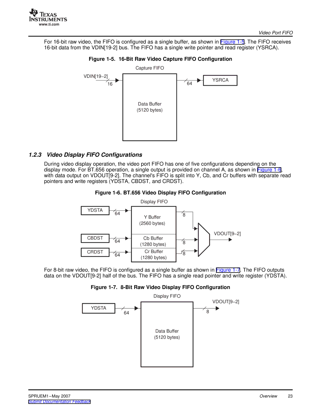
For
Figure 1-5. 16-Bit Raw Video Capture FIFO Configuration
VDIN[19−2]
16
Capture FIFO
Data Buffer (5120 bytes)
64
YSRCA
1.2.3 Video Display FIFO Configurations
During video display operation, the video port FIFO has one of five configurations depending on the display mode. For BT.656 operation, a single output is provided on channel A, as shown in Figure
Figure 1-6. BT.656 Video Display FIFO Configuration
YDSTA
CBDST
CRDST
64
64
64
Display FIFO
YBuffer
(2560 bytes)
Cb Buffer
(1280 bytes)
Cr Buffer (1280 bytes)
8 |
8 |
8 |
VDOUT[9−2]
For
Figure 1-7. 8-Bit Raw Video Display FIFO Configuration
YDSTA ![]() 64
64
Display FIFO
Data Buffer (5120 bytes)
VDOUT[9−2]
8
SPRUEM1 | Overview | 23 |