www.ti.com
|
|
|
| Video Port Control Registers | |
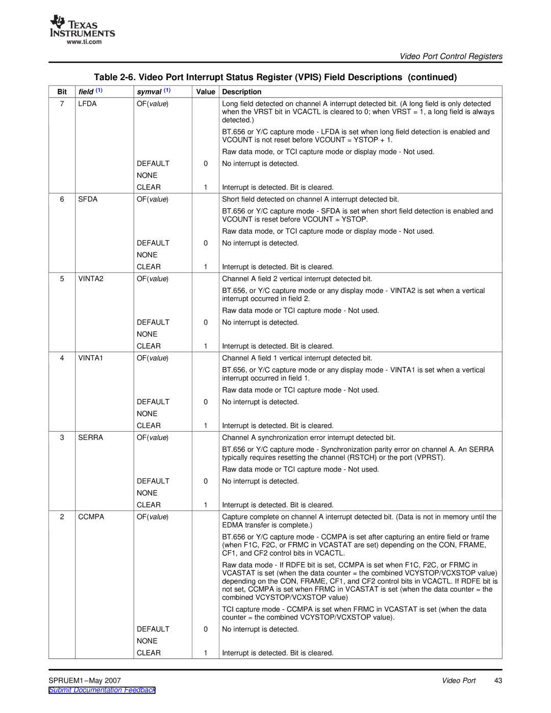
| Table |
| |||
Bit | field (1) | symval (1) | Value | Description |
|
7 | LFDA | OF(value) |
| Long field detected on channel A interrupt detected bit. (A long field is only detected |
|
|
|
|
| when the VRST bit in VCACTL is cleared to 0; when VRST = 1, a long field is always | |
|
|
|
| detected.) |
|
|
|
|
| BT.656 or Y/C capture mode - LFDA is set when long field detection is enabled and |
|
|
|
|
| VCOUNT is not reset before VCOUNT = YSTOP + 1. |
|
|
|
|
| Raw data mode, or TCI capture mode or display mode - Not used. |
|
|
| DEFAULT | 0 | No interrupt is detected. |
|
|
| NONE |
|
|
|
|
| CLEAR | 1 | Interrupt is detected. Bit is cleared. |
|
6 | SFDA | OF(value) |
| Short field detected on channel A interrupt detected bit. |
|
|
|
|
| BT.656 or Y/C capture mode - SFDA is set when short field detection is enabled and |
|
|
|
|
| VCOUNT is reset before VCOUNT = YSTOP. |
|
|
|
|
| Raw data mode, or TCI capture mode or display mode - Not used. |
|
|
| DEFAULT | 0 | No interrupt is detected. |
|
|
| NONE |
|
|
|
|
| CLEAR | 1 | Interrupt is detected. Bit is cleared. |
|
5 | VINTA2 | OF(value) |
| Channel A field 2 vertical interrupt detected bit. |
|
|
|
|
| BT.656, or Y/C capture mode or any display mode - VINTA2 is set when a vertical |
|
|
|
|
| interrupt occurred in field 2. |
|
|
|
|
| Raw data mode or TCI capture mode - Not used. |
|
|
| DEFAULT | 0 | No interrupt is detected. |
|
|
| NONE |
|
|
|
|
| CLEAR | 1 | Interrupt is detected. Bit is cleared. |
|
4 | VINTA1 | OF(value) |
| Channel A field 1 vertical interrupt detected bit. |
|
|
|
|
| BT.656, or Y/C capture mode or any display mode - VINTA1 is set when a vertical |
|
|
|
|
| interrupt occurred in field 1. |
|
|
|
|
| Raw data mode or TCI capture mode - Not used. |
|
|
| DEFAULT | 0 | No interrupt is detected. |
|
|
| NONE |
|
|
|
|
| CLEAR | 1 | Interrupt is detected. Bit is cleared. |
|
3 | SERRA | OF(value) |
| Channel A synchronization error interrupt detected bit. |
|
|
|
|
| BT.656 or Y/C capture mode - Synchronization parity error on channel A. An SERRA |
|
|
|
|
| typically requires resetting the channel (RSTCH) or the port (VPRST). |
|
|
|
|
| Raw data mode or TCI capture mode - Not used. |
|
|
| DEFAULT | 0 | No interrupt is detected. |
|
|
| NONE |
|
|
|
|
| CLEAR | 1 | Interrupt is detected. Bit is cleared. |
|
2 | CCMPA | OF(value) |
| Capture complete on channel A interrupt detected bit. (Data is not in memory until the | |
|
|
|
| EDMA transfer is complete.) |
|
|
|
|
| BT.656 or Y/C capture mode - CCMPA is set after capturing an entire field or frame |
|
|
|
|
| (when F1C, F2C, or FRMC in VCASTAT are set) depending on the CON, FRAME, |
|
|
|
|
| CF1, and CF2 control bits in VCACTL. |
|
|
|
|
| Raw data mode - If RDFE bit is set, CCMPA is set when F1C, F2C, or FRMC in |
|
|
|
|
| VCASTAT is set (when the data counter = the combined VCYSTOP/VCXSTOP value) | |
|
|
|
| depending on the CON, FRAME, CF1, and CF2 control bits in VCACTL. If RDFE bit is | |
|
|
|
| not set, CCMPA is set when FRMC in VCASTAT is set (when the data counter = the |
|
|
|
|
| combined VCYSTOP/VCXSTOP value) |
|
|
|
|
| TCI capture mode - CCMPA is set when FRMC in VCASTAT is set (when the data |
|
|
|
|
| counter = the combined VCYSTOP/VCXSTOP value). |
|
|
| DEFAULT | 0 | No interrupt is detected. |
|
|
| NONE |
|
|
|
|
| CLEAR | 1 | Interrupt is detected. Bit is cleared. |
|
SPRUEM1 |
|
| Video Port | 43 | |
Submit Documentation Feedback |
|
|
| ||