www.ti.com
TCI Capture Mode
Table 3-12. TCI Capture Mode Operation (continued)
| VCACTL Bit |
|
| |
CON | FRAME | CF2 | CF1 | Operation |
0 | 1 | x | x | Single packet capture. FRMC is set after packet capture and causes CCMPA |
|
|
|
| to be set. Capture is halted until the FRMC bit is cleared. |
1 | 0 | x | x | Continuous packet capture. FRMC is set after packet capture and causes |
|
|
|
| CCMPA to be set (CCMPx interrupt can be disabled). The port will continue |
|
|
|
| capturing packets regardless of the state of FRMC. |
1 | 1 | x | x | Reserved |
3.8.6 Writing to the FIFO
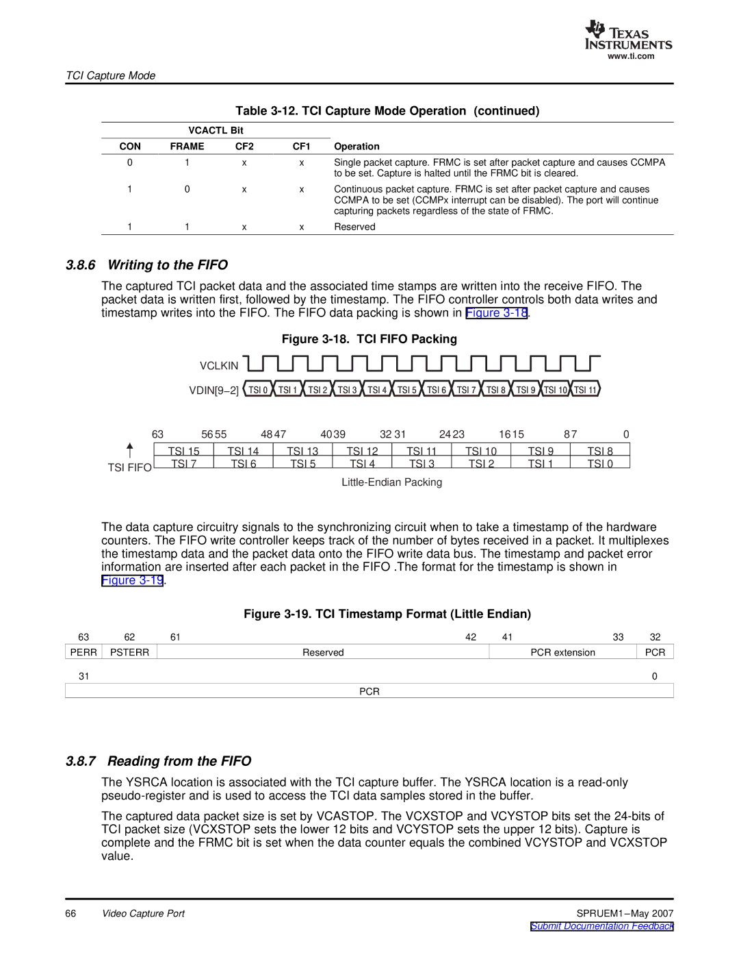
The captured TCI packet data and the associated time stamps are written into the receive FIFO. The packet data is written first, followed by the timestamp. The FIFO controller controls both data writes and timestamp writes into the FIFO. The FIFO data packing is shown in Figure
Figure 3-18. TCI FIFO Packing
VCLKIN
VDIN[9−2] ![]() TSI 0
TSI 0![]() TSI 1
TSI 1![]() TSI 2
TSI 2![]() TSI 3
TSI 3![]() TSI 4
TSI 4![]() TSI 5
TSI 5![]() TSI 6
TSI 6![]() TSI 7
TSI 7![]() TSI 8
TSI 8![]() TSI 9
TSI 9![]() TSI 10 TSI 11
TSI 10 TSI 11
|
| 63 | 56 55 | 48 47 | 4039 | 32 31 | 24 23 | 1615 | 87 | 0 | ||||||||
|
|
| TSI 15 |
| TSI 14 |
| TSI 13 |
| TSI 12 |
|
| TSI 11 |
| TSI 10 |
| TSI 9 |
| TSI 8 |
TSI FIFO |
| TSI 7 |
| TSI 6 |
| TSI 5 |
| TSI 4 |
|
| TSI 3 |
| TSI 2 |
| TSI 1 |
| TSI 0 | |
|
|
|
|
|
|
|
|
|
|
|
| |||||||
|
|
|
|
|
|
|
|
|
|
|
|
|
| |||||
The data capture circuitry signals to the synchronizing circuit when to take a timestamp of the hardware counters. The FIFO write controller keeps track of the number of bytes received in a packet. It multiplexes the timestamp data and the packet data onto the FIFO write data bus. The timestamp and packet error information are inserted after each packet in the FIFO .The format for the timestamp is shown in
Figure
Figure 3-19. TCI Timestamp Format (Little Endian)
63 | 62 | 61 | 42 | 41 | 33 | 32 |
PERR | PSTERR | Reserved |
| PCR extension |
| PCR |
31 |
|
|
|
|
| 0 |
|
|
| PCR |
|
|
|
3.8.7 Reading from the FIFO
The YSRCA location is associated with the TCI capture buffer. The YSRCA location is a
The captured data packet size is set by VCASTOP. The VCXSTOP and VCYSTOP bits set the
66 | Video Capture Port | SPRUEM1 |