www.ti.com
Video Capture Registers
3.13.7 Video Capture Channel x Vertical Interrupt Register (VCxVINT)
The video capture channel x vertical interrupt register (VCAVINT, VCBVINT) controls the generation of vertical interrupts in each field.
In BT.656 or Y/C mode, an interrupt can be generated upon completion of the specified line in a field (end of line when VCOUNT = VINTn). This allows the software to synchronize to the frame or field. The interrupt can be programmed to occur in one or both fields (or not at all) using the VIF1 and VIF2 bits. The VINTn bits also determine when the FSYNC bit in VCxSTAT is cleared. If FSCL2 is 0, then the FSYNC bit is cleared in field 1 when VCOUNT = VINT1; if FSCL2 is 1, then the FSYNC bit is cleared in field 2 when VCOUNT = VINT2.
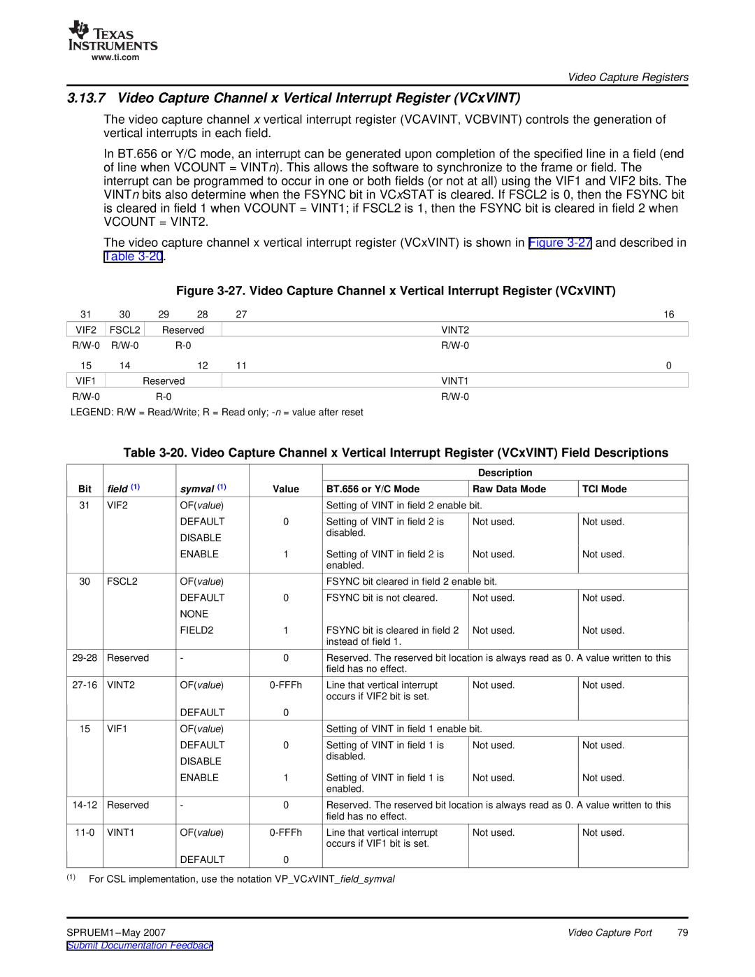
The video capture channel x vertical interrupt register (VCxVINT) is shown in Figure
Figure 3-27. Video Capture Channel x Vertical Interrupt Register (VCxVINT)
31 | 30 | 29 | 28 | 27 | 16 |
VIF2 | FSCL2 | Reserved |
| VINT2 | |
|
| ||||
15 | 14 |
| 12 | 11 | 0 |
VIF1 |
| Reserved |
|
| VINT1 |
|
|
| |||
LEGEND: R/W = Read/Write; R = Read only;
Table
|
|
|
|
| Description |
|
Bit | field (1) | symval (1) | Value | BT.656 or Y/C Mode | Raw Data Mode | TCI Mode |
31 | VIF2 | OF(value) |
| Setting of VINT in field 2 enable bit. |
| |
|
| DEFAULT | 0 | Setting of VINT in field 2 is | Not used. | Not used. |
|
| DISABLE |
| disabled. |
|
|
|
|
|
|
|
| |
|
| ENABLE | 1 | Setting of VINT in field 2 is | Not used. | Not used. |
|
|
|
| enabled. |
|
|
30 | FSCL2 | OF(value) |
| FSYNC bit cleared in field 2 enable bit. |
| |
|
| DEFAULT | 0 | FSYNC bit is not cleared. | Not used. | Not used. |
|
| NONE |
|
|
|
|
|
| FIELD2 | 1 | FSYNC bit is cleared in field 2 | Not used. | Not used. |
|
|
|
| instead of field 1. |
|
|
Reserved | - | 0 | Reserved. The reserved bit location is always read as 0. A value written to this | |||
|
|
|
| field has no effect. |
|
|
VINT2 | OF(value) | Line that vertical interrupt | Not used. | Not used. | ||
|
|
|
| occurs if VIF2 bit is set. |
|
|
|
| DEFAULT | 0 |
|
|
|
15 | VIF1 | OF(value) |
| Setting of VINT in field 1 enable bit. |
| |
|
| DEFAULT | 0 | Setting of VINT in field 1 is | Not used. | Not used. |
|
| DISABLE |
| disabled. |
|
|
|
|
|
|
|
| |
|
| ENABLE | 1 | Setting of VINT in field 1 is | Not used. | Not used. |
|
|
|
| enabled. |
|
|
Reserved | - | 0 | Reserved. The reserved bit location is always read as 0. A value written to this | |||
|
|
|
| field has no effect. |
|
|
VINT1 | OF(value) | Line that vertical interrupt | Not used. | Not used. | ||
|
|
|
| occurs if VIF1 bit is set. |
|
|
|
| DEFAULT | 0 |
|
|
|
(1)For CSL implementation, use the notation VP_VCxVINT_field_symval
SPRUEM1 | Video Capture Port | 79 |
Submit Documentation Feedback |
|
|