www.ti.com
Video Display Mode Selection
4.1Video Display Mode Selection
The video display module operates in one of three modes as listed in Table
Table 4-1. Video Display Mode Selection
DMODE Bits | Mode | Description |
000 | Digital video output is in YCbCr 4:2:2 with | |
|
| BT.656 format. |
010 | ||
100 | Digital video is output in YCbCr 4:2:2 with | |
|
| Cb/Cr multiplexed channels. |
110 |
4.1.1 Image Timing
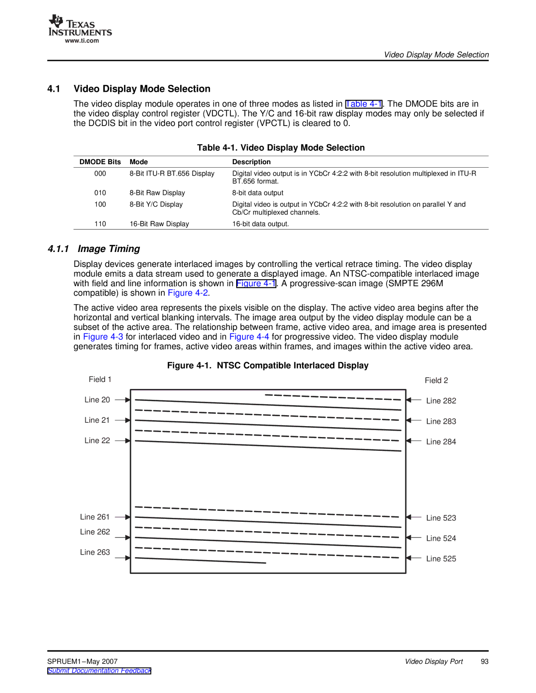
Display devices generate interlaced images by controlling the vertical retrace timing. The video display module emits a data stream used to generate a displayed image. An
The active video area represents the pixels visible on the display. The active video area begins after the horizontal and vertical blanking intervals. The image area output by the video display module can be a subset of the active area. The relationship between frame, active video area, and image area is presented in Figure
Figure 4-1. NTSC Compatible Interlaced Display
Field 1
Line 20
Line 21
Line 22
Line 261
Line 262
Line 263
Field 2
Line 282
Line 283
Line 284
Line 523
Line 524
Line 525
SPRUEM1 | Video Display Port | 93 |