www.ti.com
Video Display Registers
Table
Bit | field (1) | symval (1) | Value | Description |
FLD2XSTART | OF(value) | Specifies the pixel on the first line of field 2 where the FLD output is asserted. | ||
|
| DEFAULT | 0 |
|
4.12.15 Video Display Threshold Register (VDTHRLD)
The video display threshold register (VDTHRLD) sets the display FIFO threshold to determine when to load more display data.
The VDTHRLDn bits determines how much space must be available in the display FIFOs before the appropriate EDMA event may be generated. The Y FIFO uses the VDTHRLDn value directly while the Cb and Cr values use ½ the VDTHRLDn value rounded up to the next double word (½ (VDTHRLDn + VTHRLDn mod 2). The EDMA transfer size must be less than the value used for each FIFO. Typically, VDTHRLDn is set to the horizontal line length rounded up to the next double word boundary. For
The VDTHRLD2 bits behaves identically to VDTHRLD1, but are used during field 2 capture. It is used only if the field 2 EDMA size needs to be different from the field 1 EDMA size for some reason (for example, different display line lengths in field 1 and field 2).
In raw display mode, the INCPIX bits determine when the frame pixel counter (FPCOUNT) is incremented
. If, for example, each output value represents the R, G, or B portion of a display pixel, then the INCPIX bits are set to 3h so that the pixel counter is incremented only on every third output clock. An INCPIX value of 0h represents a count of 16 rather than 0.
The video display threshold register (VDTHRLD) is shown in Figure
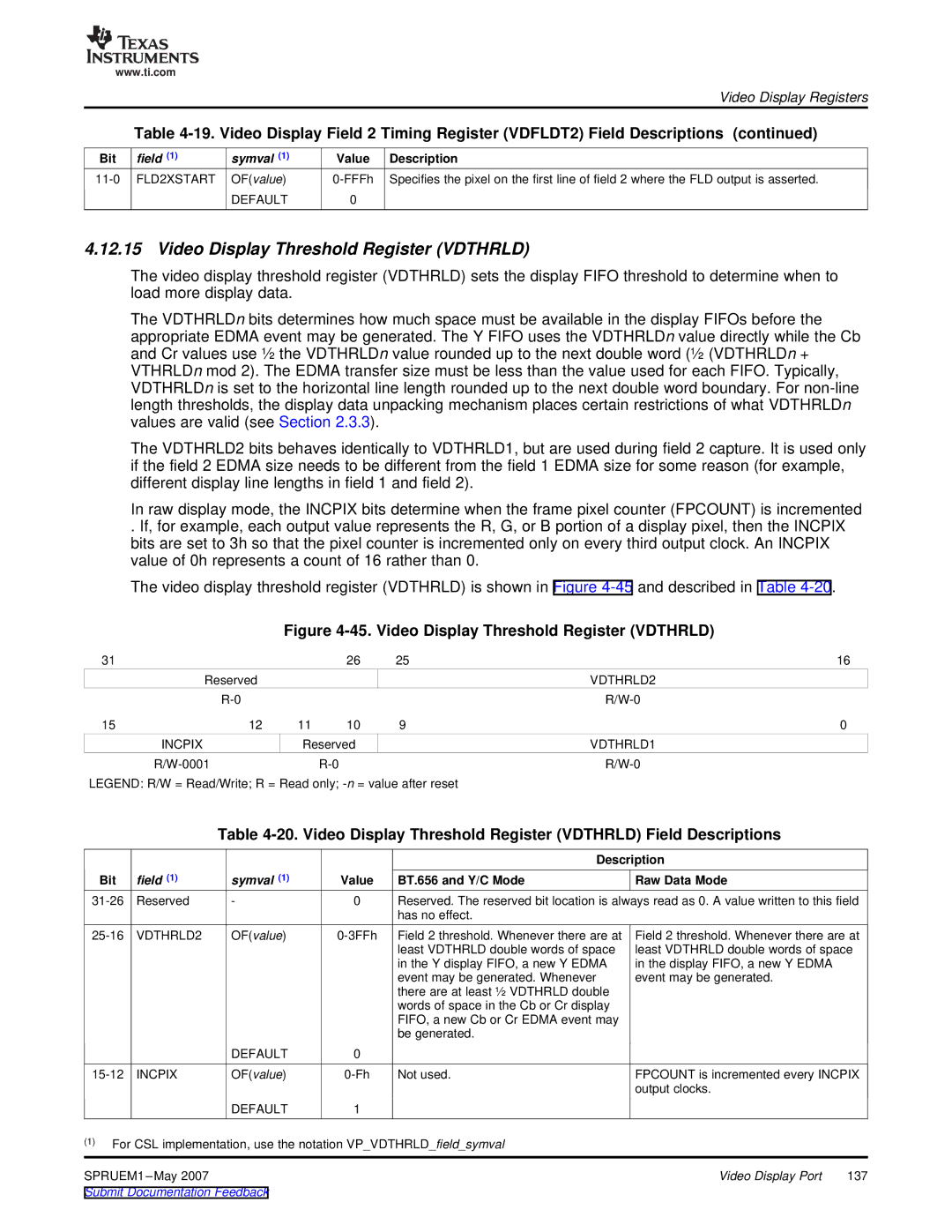
Figure 4-45. Video Display Threshold Register (VDTHRLD)
31 |
|
| 26 | 25 | 16 |
| Reserved |
|
|
| VDTHRLD2 |
|
|
|
| ||
15 | 12 | 11 | 10 | 9 | 0 |
| INCPIX | Reserved |
| VDTHRLD1 | |
|
|
| |||
LEGEND: R/W = Read/Write; R = Read only;
Table
|
|
|
|
| Description |
Bit | field (1) | symval (1) | Value | BT.656 and Y/C Mode | Raw Data Mode |
Reserved | - | 0 | Reserved. The reserved bit location is always read as 0. A value written to this field | ||
|
|
|
| has no effect. |
|
VDTHRLD2 | OF(value) | Field 2 threshold. Whenever there are at | ||
|
|
|
| least VDTHRLD double words of space |
|
|
|
| in the Y display FIFO, a new Y EDMA |
|
|
|
| event may be generated. Whenever |
|
|
|
| there are at least ½ VDTHRLD double |
|
|
|
| words of space in the Cb or Cr display |
|
|
|
| FIFO, a new Cb or Cr EDMA event may |
|
|
|
| be generated. |
|
| DEFAULT | 0 |
|
INCPIX | OF(value) | Not used. | ||
|
| DEFAULT | 1 |
|
Field 2 threshold. Whenever there are at least VDTHRLD double words of space in the display FIFO, a new Y EDMA event may be generated.
FPCOUNT is incremented every INCPIX output clocks.
(1)For CSL implementation, use the notation VP_VDTHRLD_field_symval
SPRUEM1 | Video Display Port | 137 |