www.ti.com
Video Port Control Registers
Table
Bit | field (1) | symval (1) | Value | Description |
3 | SERRA | OF(value) |
| Channel A synchronization error interrupt enable bit. |
|
| DEFAULT | 0 | Interrupt is disabled. |
|
| DISABLE |
|
|
|
| ENABLE | 1 | Interrupt is enabled. |
2 | CCMPA | OF(value) |
| Capture complete on channel A interrupt enable bit. |
|
| DEFAULT | 0 | Interrupt is disabled. |
|
| DISABLE |
|
|
|
| ENABLE | 1 | Interrupt is enabled. |
1 | COVRA | OF(value) |
| Capture overrun on channel A interrupt enable bit. |
|
| DEFAULT | 0 | Interrupt is disabled. |
|
| DISABLE |
|
|
|
| ENABLE | 1 | Interrupt is enabled. |
0 | VIE | OF(value) |
| Video port global interrupt enable bit. Must be set for interrupt to be sent to DSP. |
|
| DEFAULT | 0 | Interrupt is disabled. |
|
| DISABLE |
|
|
|
| ENABLE | 1 | Interrupt is enabled. |
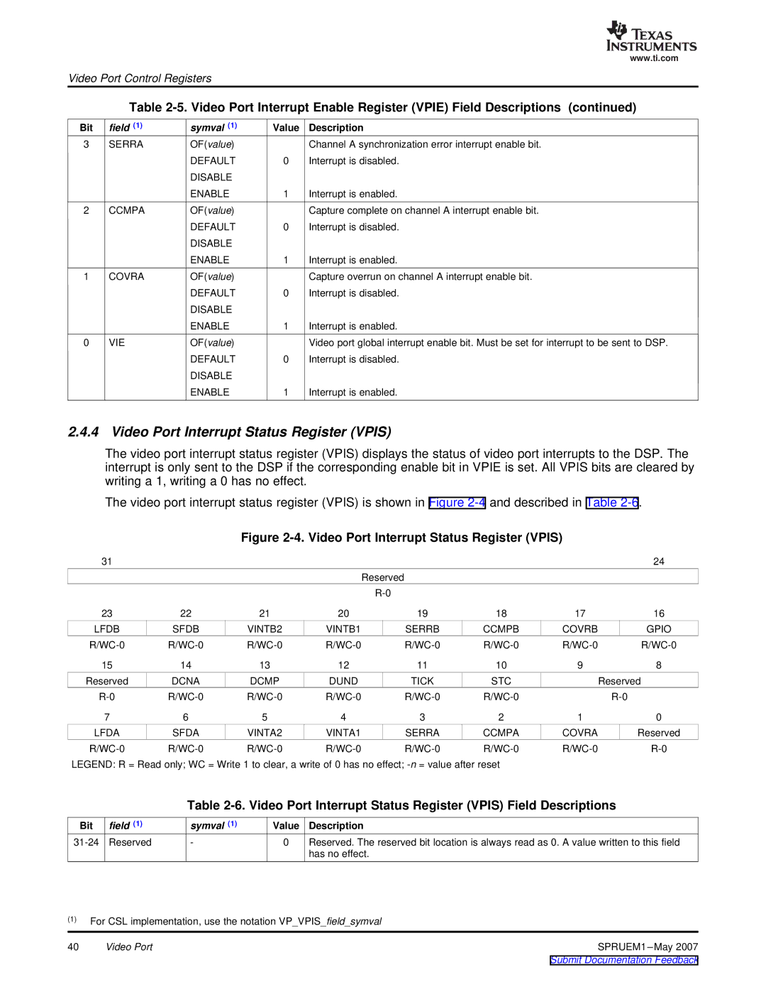
2.4.4 Video Port Interrupt Status Register (VPIS)
The video port interrupt status register (VPIS) displays the status of video port interrupts to the DSP. The interrupt is only sent to the DSP if the corresponding enable bit in VPIE is set. All VPIS bits are cleared by writing a 1, writing a 0 has no effect.
The video port interrupt status register (VPIS) is shown in Figure
Figure 2-4. Video Port Interrupt Status Register (VPIS)
31 |
|
|
|
|
|
| 24 |
|
|
|
| Reserved |
|
|
|
|
|
|
|
|
|
| |
23 | 22 | 21 | 20 | 19 | 18 | 17 | 16 |
LFDB | SFDB | VINTB2 | VINTB1 | SERRB | CCMPB | COVRB | GPIO |
15 | 14 | 13 | 12 | 11 | 10 | 9 | 8 |
Reserved | DCNA | DCMP | DUND | TICK | STC |
| Reserved |
| |||||||
7 | 6 | 5 | 4 | 3 | 2 | 1 | 0 |
LFDA | SFDA | VINTA2 | VINTA1 | SERRA | CCMPA | COVRA | Reserved |
LEGEND: R = Read only; WC = Write 1 to clear, a write of 0 has no effect;
Table
Bit | field (1) | symval (1) | Value | Description |
Reserved | - | 0 | Reserved. The reserved bit location is always read as 0. A value written to this field | |
|
|
|
| has no effect. |
(1)For CSL implementation, use the notation VP_VPIS_field_symval
40 | Video Port | SPRUEM1 |
|
| Submit Documentation Feedback |