www.ti.com
Video Capture Registers
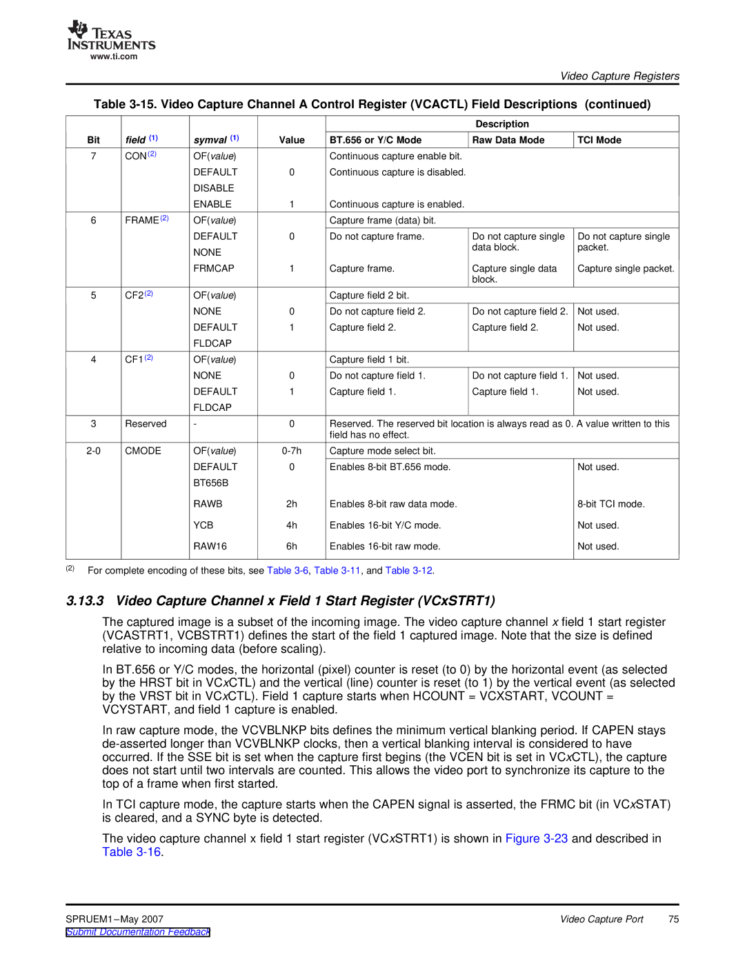
Table
|
|
|
|
| Description |
|
Bit | field (1) | symval (1) | Value | BT.656 or Y/C Mode | Raw Data Mode | TCI Mode |
7 | CON(2) | OF(value) |
| Continuous capture enable bit. |
|
|
|
| DEFAULT | 0 | Continuous capture is disabled. |
|
|
|
| DISABLE |
|
|
|
|
|
| ENABLE | 1 | Continuous capture is enabled. |
|
|
6 | FRAME(2) | OF(value) |
| Capture frame (data) bit. |
|
|
|
| DEFAULT | 0 | Do not capture frame. | Do not capture single | Do not capture single |
|
| NONE |
|
| data block. | packet. |
|
|
|
|
|
| |
|
| FRMCAP | 1 | Capture frame. | Capture single data | Capture single packet. |
|
|
|
|
| block. |
|
5 | CF2(2) | OF(value) |
| Capture field 2 bit. |
|
|
|
| NONE | 0 | Do not capture field 2. | Do not capture field 2. | Not used. |
|
| DEFAULT | 1 | Capture field 2. | Capture field 2. | Not used. |
|
| FLDCAP |
|
|
|
|
4 | CF1(2) | OF(value) |
| Capture field 1 bit. |
|
|
|
| NONE | 0 | Do not capture field 1. | Do not capture field 1. | Not used. |
|
| DEFAULT | 1 | Capture field 1. | Capture field 1. | Not used. |
|
| FLDCAP |
|
|
|
|
3 | Reserved | - | 0 | Reserved. The reserved bit location is always read as 0. A value written to this | ||
|
|
|
| field has no effect. |
|
|
CMODE | OF(value) | Capture mode select bit. |
|
| ||
|
| DEFAULT | 0 | Enables |
| Not used. |
|
| BT656B |
|
|
|
|
|
| RAWB | 2h | Enables |
| |
|
| YCB | 4h | Enables |
| Not used. |
|
| RAW16 | 6h | Enables |
| Not used. |
(2)For complete encoding of these bits, see Table
3.13.3 Video Capture Channel x Field 1 Start Register (VCxSTRT1)
The captured image is a subset of the incoming image. The video capture channel x field 1 start register (VCASTRT1, VCBSTRT1) defines the start of the field 1 captured image. Note that the size is defined relative to incoming data (before scaling).
In BT.656 or Y/C modes, the horizontal (pixel) counter is reset (to 0) by the horizontal event (as selected by the HRST bit in VCxCTL) and the vertical (line) counter is reset (to 1) by the vertical event (as selected by the VRST bit in VCxCTL). Field 1 capture starts when HCOUNT = VCXSTART, VCOUNT = VCYSTART, and field 1 capture is enabled.
In raw capture mode, the VCVBLNKP bits defines the minimum vertical blanking period. If CAPEN stays
In TCI capture mode, the capture starts when the CAPEN signal is asserted, the FRMC bit (in VCxSTAT) is cleared, and a SYNC byte is detected.
The video capture channel x field 1 start register (VCxSTRT1) is shown in Figure
SPRUEM1 | Video Capture Port | 75 |
