www.ti.com
Video Port
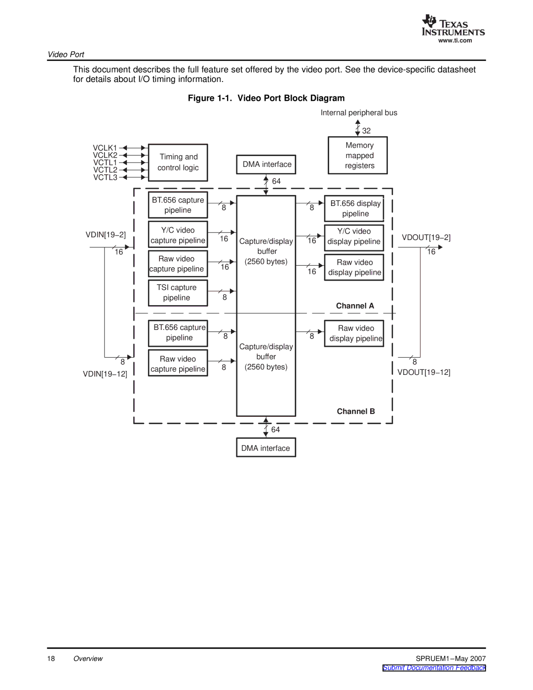
This document describes the full feature set offered by the video port. See the
Figure 1-1. Video Port Block Diagram
VCLK1
VCLK2
VCTL1
VCTL2
VCTL3
Timing and control logic
DMA interface
64
Internal peripheral bus
![]() 32
32
Memory mapped registers
VDIN[19−2]
16
8
VDIN[19−12]
BT.656 capture |
|
| |
|
| ||
pipeline | 8 |
| |
|
| ||
|
|
| |
|
|
| |
Y/C video |
|
| |
capture pipeline | 16 | Capture/display | |
|
| buffer | |
Raw video |
| ||
| (2560 bytes) | ||
capture pipeline | 16 | ||
| |||
|
|
| |
|
|
| |
TSI capture |
|
| |
pipeline | 8 |
| |
|
|
| |
|
|
| |
|
|
| |
BT.656 capture |
|
| |
pipeline | 8 |
| |
|
| Capture/display | |
|
| ||
Raw video |
| buffer | |
8 | (2560 bytes) | ||
capture pipeline | |||
|
|
| |
|
|
|
![]() 64
64
![]() 8
8 ![]() BT.656 display pipeline
BT.656 display pipeline
Y/C video
16 display pipeline
Raw video
16 display pipeline
Channel A
8 | Raw video | |
display pipeline | ||
| ||
|
|
Channel B
VDOUT[19−2]
16
8
VDOUT[19−12]
DMA interface
18 | Overview | SPRUEM1 |