www.ti.com
Video Display Registers
Table
(continued)
Bit | field (1) | symval (1) | Value | Description |
Reserved | - | 0 | Reserved. The reserved bit location is always read as 0. A value written to this | |
|
|
|
| field has no effect. |
VSYNCXSTOP1 | OF(value) | Specifies the pixel where VSYNC is | ||
|
| DEFAULT | 0 |
|
4.12.19 Video Display Field 2 Vertical Synchronization Start Register (VDVSYNS2)
The video display field 2 vertical synchronization start register (VDVSYNS2) controls the start of vertical synchronization in field 2. The VDVSYNS2 is shown in Figure
Generation of the vertical synchronization is shown in Figure
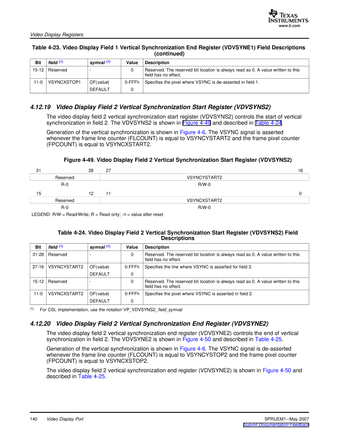
Figure 4-49. Video Display Field 2 Vertical Synchronization Start Register (VDVSYNS2)
31 | 28 | 27 | 16 |
| Reserved |
| VSYNCYSTART2 |
|
| ||
15 | 12 | 11 | 0 |
| Reserved |
| VSYNCXSTART2 |
|
|
LEGEND: R/W = Read/Write; R = Read only;
Table
Descriptions
Bit | field (1) | symval (1) | Value | Description |
Reserved | - | 0 | Reserved. The reserved bit location is always read as 0. A value written to this | |
|
|
|
| field has no effect. |
VSYNCYSTART2 | OF(value) | Specifies the line where VSYNC is asserted for field 2. | ||
|
| DEFAULT | 0 |
|
Reserved | - | 0 | Reserved. The reserved bit location is always read as 0. A value written to this | |
|
|
|
| field has no effect. |
VSYNCXSTART2 | OF(value) | Specifies the pixel where VSYNC is asserted in field 2. | ||
|
| DEFAULT | 0 |
|
(1)For CSL implementation, use the notation VP_VDVSYNS2_field_symval
4.12.20 Video Display Field 2 Vertical Synchronization End Register (VDVSYNE2)
The video display field 2 vertical synchronization end register (VDVSYNE2) controls the end of vertical synchronization in field 2. The VDVSYNE2 is shown in Figure
Generation of the vertical synchronization is shown in Figure
The video display field 2 vertical synchronization end register (VDVSYNE2) is shown in Figure
140 | Video Display Port | SPRUEM1 |