www.ti.com
|
|
|
|
|
|
|
|
|
|
|
|
|
|
|
|
|
|
|
|
|
|
|
|
|
|
|
|
|
|
|
|
|
|
|
|
|
|
|
|
|
|
|
|
|
|
|
|
|
|
|
|
| TCI Capture Mode | ||||
|
|
|
|
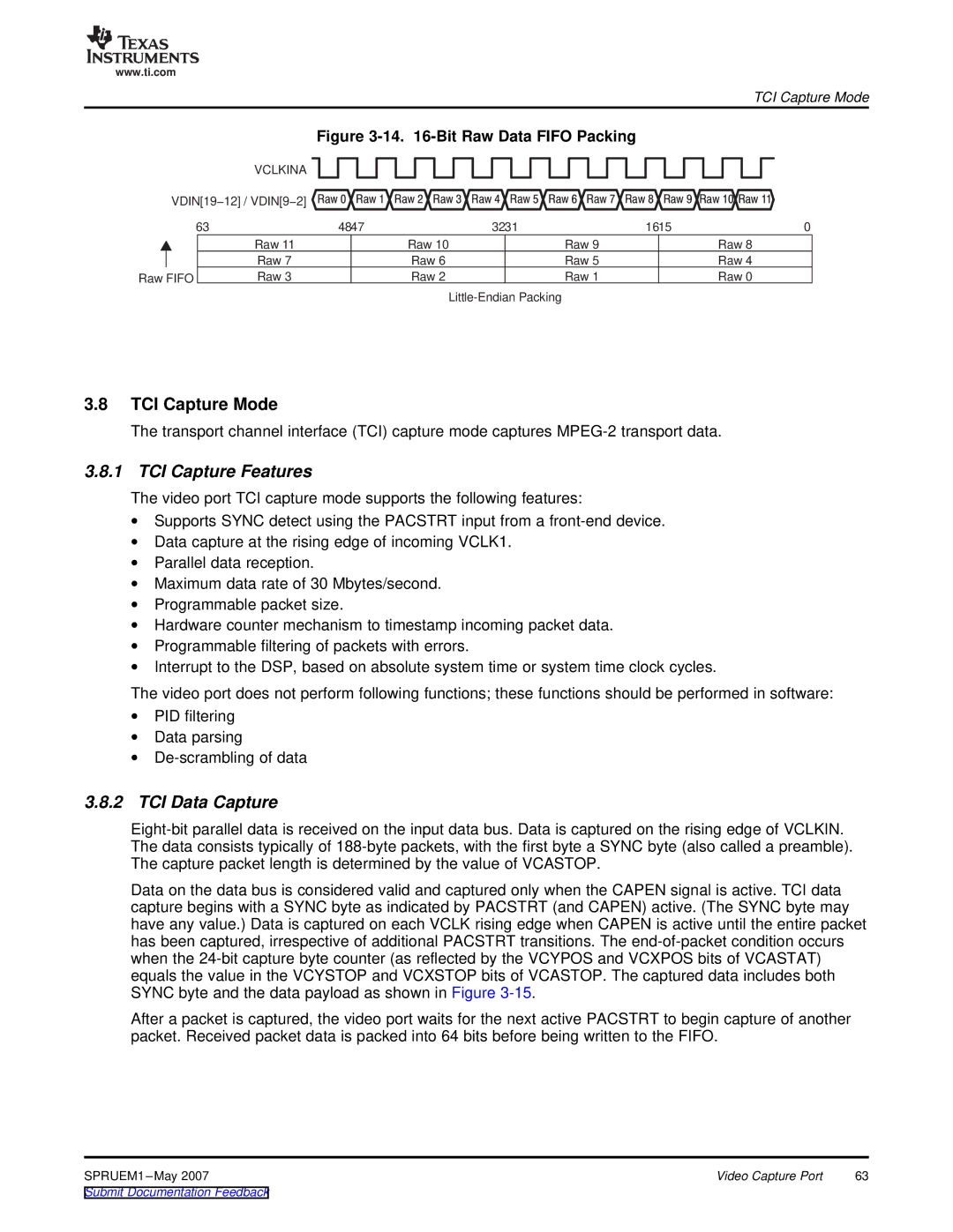
| Figure |
|
|
|
|
|
|
|
|
|
|
|
| ||||||||||||||||||||||||||||||||||||||||
|
|
| VCLKINA |
|
|
|
|
|
|
|
|
|
|
|
|
|
|
|
|
|
|
|
|
|
|
|
|
|
|
|
|
|
|
|
|
|
|
|
|
|
|
|
|
|
|
|
|
|
|
|
|
|
|
|
|
|
|
|
|
|
|
|
|
|
|
|
|
|
|
|
|
|
|
|
|
|
|
|
|
|
|
|
|
|
|
|
|
|
|
|
|
|
|
|
|
|
|
|
|
|
|
|
|
|
|
|
|
|
|
|
|
|
|
| |
| VDIN[19−12] / VDIN[9−2] |
|
|
|
|
|
|
|
|
|
|
|
|
|
|
|
|
|
|
|
|
|
|
|
|
|
|
|
|
|
|
|
|
|
|
|
|
|
|
|
|
|
|
|
|
|
|
|
|
|
|
|
|
|
| ||
|
| Raw 0 Raw | 1 Raw 2 Raw 3 Raw 4 Raw | 5 Raw 6 Raw 7 Raw 8 Raw | 9Raw 10Raw 11 | ||||||||||||||||||||||||||||||||||||||||||||||||||||
|
|
|
|
|
|
|
|
|
|
|
|
|
|
|
|
|
|
|
|
|
|
|
|
|
|
|
|
|
|
|
|
|
|
|
|
|
|
|
|
|
|
|
|
|
|
|
|
|
|
|
|
|
|
| |||
63 |
| 4847 | 3231 | 1615 | 0 |
| |||||||||||||||||||||||||||||||||||||||||||||||||||
|
|
| Raw 11 |
|
|
|
|
|
|
|
|
|
|
| Raw 10 |
|
|
|
| Raw 9 |
|
|
|
| Raw 8 |
| |||||||||||||||||||||||||||||||
|
|
|
|
|
|
|
|
|
|
| |||||||||||||||||||||||||||||||||||||||||||||||
|
|
| Raw 7 |
|
|
|
|
|
|
|
|
|
|
| Raw 6 |
|
|
|
| Raw 5 |
|
|
|
| Raw 4 |
| |||||||||||||||||||||||||||||||
Raw FIFO |
| Raw 3 |
|
|
|
|
|
|
|
|
|
|
| Raw 2 |
|
|
|
| Raw 1 |
|
|
|
| Raw 0 |
| ||||||||||||||||||||||||||||||||
|
|
|
|
|
|
|
|
|
|
|
|
|
|
|
|
|
|
|
|
|
|
|
|
|
|
|
|
|
|
| |||||||||||||||||||||||||||
3.8TCI Capture Mode
The transport channel interface (TCI) capture mode captures
3.8.1 TCI Capture Features
The video port TCI capture mode supports the following features:
∙Supports SYNC detect using the PACSTRT input from a
∙Data capture at the rising edge of incoming VCLK1.
∙Parallel data reception.
∙Maximum data rate of 30 Mbytes/second.
∙Programmable packet size.
∙Hardware counter mechanism to timestamp incoming packet data.
∙Programmable filtering of packets with errors.
∙Interrupt to the DSP, based on absolute system time or system time clock cycles.
The video port does not perform following functions; these functions should be performed in software:
∙PID filtering
∙Data parsing
∙
3.8.2TCI Data Capture
Data on the data bus is considered valid and captured only when the CAPEN signal is active. TCI data capture begins with a SYNC byte as indicated by PACSTRT (and CAPEN) active. (The SYNC byte may have any value.) Data is captured on each VCLK rising edge when CAPEN is active until the entire packet has been captured, irrespective of additional PACSTRT transitions. The
After a packet is captured, the video port waits for the next active PACSTRT to begin capture of another packet. Received packet data is packed into 64 bits before being written to the FIFO.
SPRUEM1 | Video Capture Port | 63 |