www.ti.com
Video Capture Registers
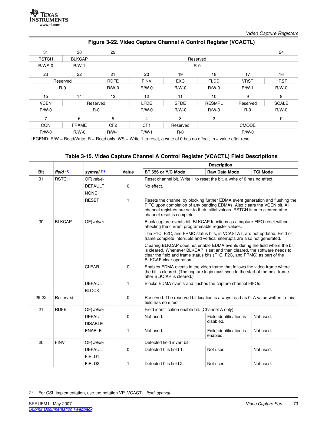
Figure 3-22. Video Capture Channel A Control Register (VCACTL)
31 |
| 30 | 29 |
|
|
|
| 24 |
RSTCH | BLKCAP |
|
|
| Reserved |
|
| |
|
|
|
|
|
| |||
23 |
| 22 | 21 | 20 | 19 | 18 | 17 | 16 |
| Reserved |
| RDFE | FINV | EXC | FLDD | VRST | HRST |
|
| |||||||
15 |
| 14 | 13 | 12 | 11 | 10 | 9 | 8 |
VCEN |
| Reserved |
| LFDE | SFDE | RESMPL | Reserved | SCALE |
|
| |||||||
7 |
| 6 | 5 | 4 | 3 | 2 |
| 0 |
CON |
| FRAME | CF2 | CF1 | Reserved | CMODE |
| |
|
|
| ||||||
LEGEND: R/W = Read/Write; R = Read only; WS = Write 1 to reset, a write of 0 has no effect;
Table
|
|
|
|
| Description |
|
Bit | field (1) | symval (1) | Value | BT.656 or Y/C Mode | Raw Data Mode | TCI Mode |
31 | RSTCH | OF(value) |
| Reset channel bit. Write 1 to reset the bit, a write of 0 has no effect. | ||
|
| DEFAULT | 0 | No effect. |
|
|
|
| NONE |
|
|
|
|
|
| RESET | 1 | Resets the channel by blocking further EDMA event generation and flushing the | ||
|
|
|
| FIFO upon completion of any pending EDMAs. Also clears the VCEN bit. All | ||
|
|
|
| channel registers are set to their initial values. RSTCH is | ||
|
|
|
| channel reset is complete. |
|
|
30 | BLKCAP | OF(value) |
| Block capture events bit. BLKCAP functions as a capture FIFO reset without | ||
|
|
|
| affecting the current programmable register values. |
| |
|
|
|
| The F1C, F2C, and FRMC status bits, in VCASTAT, are not updated. Field or | ||
|
|
|
| frame complete interrupts and vertical interrupts are also not generated. | ||
|
|
|
| Clearing BLKCAP does not enable EDMA events during the field where the bit | ||
|
|
|
| is cleared. Whenever BLKCAP is set and then cleared, the software needs to | ||
|
|
|
| clear the field and frame status bits (F1C, F2C, and FRMC) as part of the | ||
|
|
|
| BLKCAP clear operation. |
|
|
|
| CLEAR | 0 | Enables EDMA events in the video frame that follows the video frame where | ||
|
|
|
| the bit is cleared. (The capture logic must sync to the start of the next frame | ||
|
|
|
| after BLKCAP is cleared.) |
|
|
|
| DEFAULT | 1 | Blocks EDMA events and flushes the capture channel FIFOs. | ||
|
| BLOCK |
|
|
|
|
Reserved | - | 0 | Reserved. The reserved bit location is always read as 0. A value written to this | |||
|
|
|
| field has no effect. |
|
|
21 | RDFE | OF(value) |
| Field identification enable bit. (Channel A only) |
| |
|
| DEFAULT | 0 | Not used. | Field identification is | Not used. |
|
| DISABLE |
|
| disabled. |
|
|
|
|
|
|
| |
|
| ENABLE | 1 | Not used. | Field identification is | Not used. |
|
|
|
|
| enabled. |
|
20 | FINV | OF(value) |
| Detected field invert bit. |
|
|
|
| DEFAULT | 0 | Detected 0 is field 1. | Not used. | Not used. |
|
| FIELD1 |
|
|
|
|
|
| FIELD2 | 1 | Detected 0 is field 2. | Not used. | Not used. |
(1)For CSL implementation, use the notation VP_VCACTL_field_symval
SPRUEM1 | Video Capture Port | 73 |
Submit Documentation Feedback |
|
|