www.ti.com
Video Capture Registers
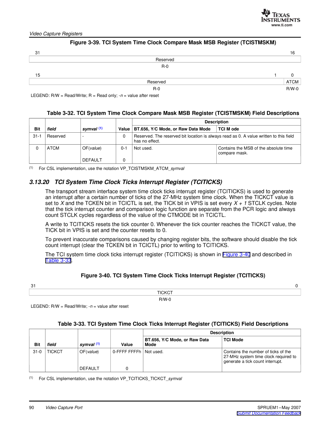
Figure 3-39. TCI System Time Clock Compare Mask MSB Register (TCISTMSKM)
31 |
| 16 |
Reserved |
|
|
|
| |
15 | 1 | 0 |
Reserved |
| ATCM |
|
LEGEND: R/W = Read/Write; R = Read only;
Table
|
|
|
| Description | |
Bit | field | symval (1) | Value | BT.656, Y/C Mode, or Raw Data Mode | TCI M ode |
Reserved | - | 0 | Reserved. The reserved bit location is always read as 0. A value written to this field | ||
|
|
|
| has no effect. |
|
0 | ATCM | OF(value) | Not used. | Contains the MSB of the absolute time | |
|
|
|
|
| compare mask. |
|
| DEFAULT | 0 |
|
|
(1)For CSL implementation, use the notation VP_TCISTMSKM_ATCM_symval
3.13.20 TCI System Time Clock Ticks Interrupt Register (TCITICKS)
The transport stream interface system time clock ticks interrupt register (TCITICKS) is used to generate an interrupt after a certain number of ticks of the
A write to TCITICKS resets the tick counter 0. Whenever the tick counter reaches the TICKCT value, the TICK bit in VPIS is set and the counter resets to 0.
To prevent inaccurate comparisons caused by changing register bits, the software should disable the tick count interrupt (clear the TCKEN bit in TCICTL) prior to writing to TCITICKS.
The TCI system time clock ticks interrupt register (TCITICKS) is shown in Figure
Figure 3-40. TCI System Time Clock Ticks Interrupt Register (TCITICKS)
31 | 0 |
TICKCT
LEGEND: R/W = Read/Write;
Table
|
|
|
|
| Description |
|
| symval (1) |
| BT.656, Y/C Mode, or Raw Data | TCI Mode |
Bit | field | Value | Mode |
| |
TICKCT | OF(value) | Not used. | Contains the number of ticks of the | ||
|
|
|
|
| |
|
|
|
|
| generate a tick count interrupt. |
|
| DEFAULT | 0 |
|
|
(1)For CSL implementation, use the notation VP_TCITICKS_TICKCT_symval
90 | Video Capture Port | SPRUEM1 |