www.ti.com
Video Capture Mode Selection
3.1Video Capture Mode Selection
The video capture module operates in one of five modes as listed in Table
When operating as a raw video capture channel, no data selection or data interpretation is performed. The
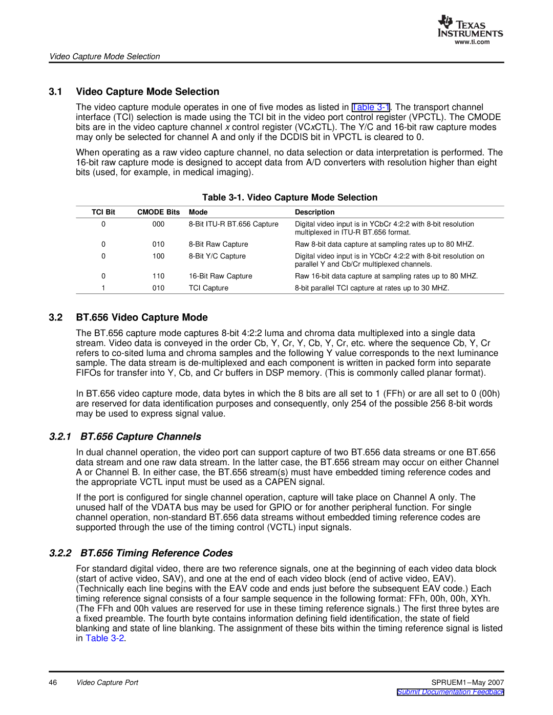
Table 3-1. Video Capture Mode Selection
TCI Bit | CMODE Bits | Mode | Description |
0 | 000 | Digital video input is in YCbCr 4:2:2 with | |
|
|
| multiplexed in |
0 | 010 | Raw | |
0 | 100 | Digital video input is in YCbCr 4:2:2 with | |
|
|
| parallel Y and Cb/Cr multiplexed channels. |
0 | 110 | Raw | |
1 | 010 | TCI Capture |
3.2BT.656 Video Capture Mode
The BT.656 capture mode captures
In BT.656 video capture mode, data bytes in which the 8 bits are all set to 1 (FFh) or are all set to 0 (00h) are reserved for data identification purposes and consequently, only 254 of the possible 256
3.2.1 BT.656 Capture Channels
In dual channel operation, the video port can support capture of two BT.656 data streams or one BT.656 data stream and one raw data stream. In the latter case, the BT.656 stream may occur on either Channel A or Channel B. In either case, the BT.656 stream(s) must have embedded timing reference codes and the appropriate VCTL input must be used as a CAPEN signal.
If the port is configured for single channel operation, capture will take place on Channel A only. The unused half of the VDATA bus may be used for GPIO or for another peripheral function. For single channel operation,
3.2.2 BT.656 Timing Reference Codes
For standard digital video, there are two reference signals, one at the beginning of each video data block (start of active video, SAV), and one at the end of each video block (end of active video, EAV). (Technically each line begins with the EAV code and ends just before the subsequent EAV code.) Each timing reference signal consists of a four sample sequence in the following format: FFh, 00h, 00h, XYh. (The FFh and 00h values are reserved for use in these timing reference signals.) The first three bytes are a fixed preamble. The fourth byte contains information defining field identification, the state of field blanking and state of line blanking. The assignment of these bits within the timing reference signal is listed in Table
46 | Video Capture Port | SPRUEM1 |