www.ti.com
BT.656 and Y/C Mode Field and Frame Operation
3.4.3 Horizontal Synchronization
Horizontal synchronization determines when the horizontal pixel/sample counter is reset. The EXC and HRST bits in VCxCTL allow you to program the event that triggers the start of a line. The encoding of these bits is shown in Table
Table 3-8. Horizontal Synchronization Programming
|
| VCxCTL Bit |
|
HMode | EXC | HRST | Horizontal Counter Reset Point |
0 | 0 | 0 | EAV code (H=1) - beginning of horizontal blanking. |
1 | 0 | 1 | SAV code (H=0) - Start of active video. |
2 | 1 | 0 | VCTL1 input active edge - beginning of horizontal blanking or horizontal sync |
|
|
| period. (VCTL1 must be configured as a horizontal control signal.) |
3 | 1 | 1 | VCTL1 input inactive edge - first active pixel on line or end of horizontal sync. |
|
|
| (VCTL1 must be configured as a horizontal control signal.) |
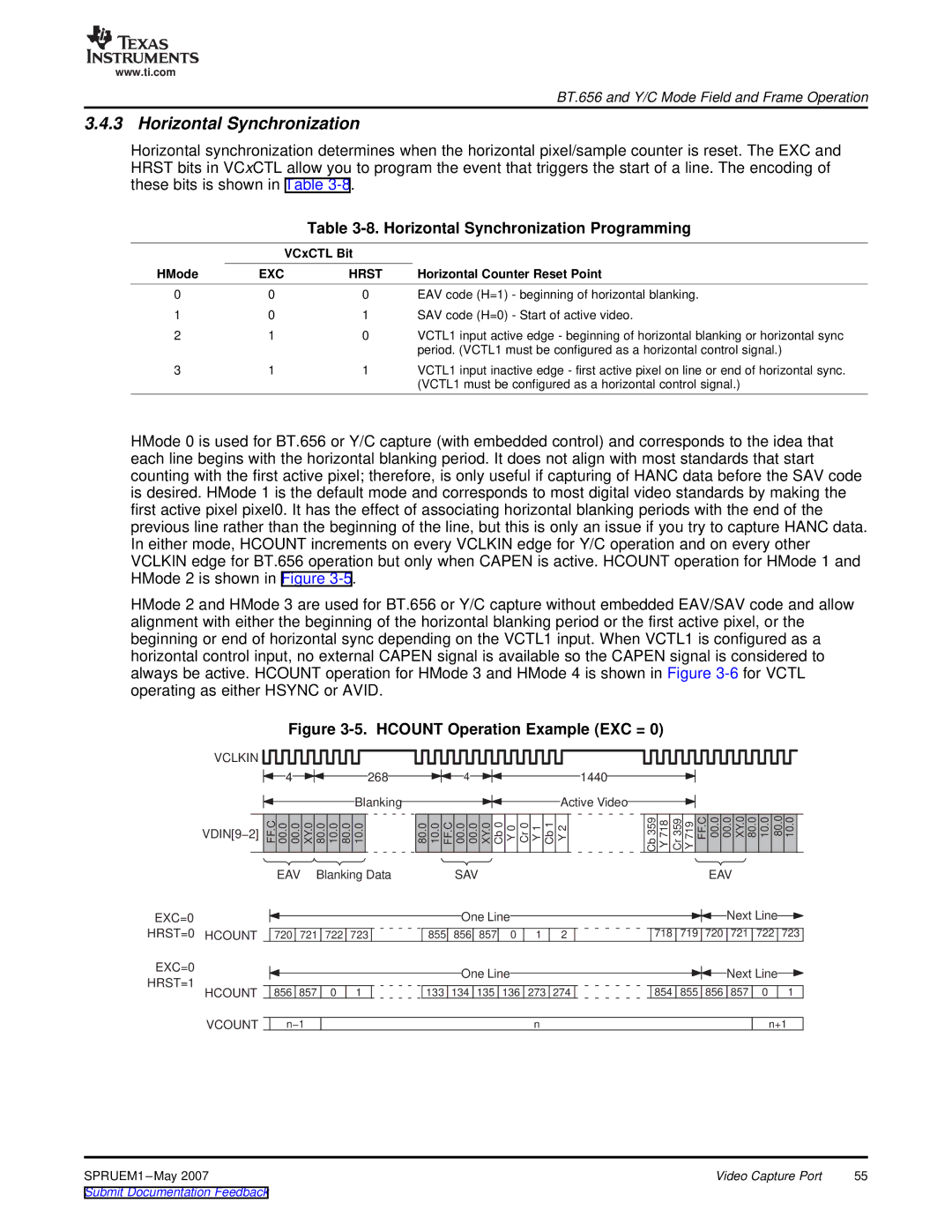
HMode 0 is used for BT.656 or Y/C capture (with embedded control) and corresponds to the idea that each line begins with the horizontal blanking period. It does not align with most standards that start counting with the first active pixel; therefore, is only useful if capturing of HANC data before the SAV code is desired. HMode 1 is the default mode and corresponds to most digital video standards by making the first active pixel pixel0. It has the effect of associating horizontal blanking periods with the end of the previous line rather than the beginning of the line, but this is only an issue if you try to capture HANC data. In either mode, HCOUNT increments on every VCLKIN edge for Y/C operation and on every other VCLKIN edge for BT.656 operation but only when CAPEN is active. HCOUNT operation for HMode 1 and HMode 2 is shown in Figure
HMode 2 and HMode 3 are used for BT.656 or Y/C capture without embedded EAV/SAV code and allow alignment with either the beginning of the horizontal blanking period or the first active pixel, or the beginning or end of horizontal sync depending on the VCTL1 input. When VCTL1 is configured as a horizontal control input, no external CAPEN signal is available so the CAPEN signal is considered to always be active. HCOUNT operation for HMode 3 and HMode 4 is shown in Figure
Figure 3-5. HCOUNT Operation Example (EXC = 0)
VCLKIN ![]()
![]()
![]()
![]()
![]()
4
268
4
1440
Blanking | Active Video |
VDIN[9−2] | FF.C 00.0 00.0 | XY.0 | 80.0 | 10.0 | 80.0 | 10.0 | 80.0 | 10.0 | FF.C 00.0 | 00.0 | XY.0 | Cb0 | Y0 | Cr0 | Y1 | Cb1 | Y2 |
|
|
|
|
|
|
|
|
|
|
|
|
|
|
|
|
|
Cb 359
Y 718
Cr 359
Y 719
FF.C
00.0
00.0
XY.0
80.0
10.0
80.0
10.0
EAV Blanking Data | SAV | EAV |
EXC=0
HRST=0 HCOUNT
EXC=0
HRST=1
HCOUNT
|
|
|
|
|
|
| One Line |
|
|
|
|
|
| Next Line |
| ||||
|
|
|
|
|
|
|
|
|
|
|
|
|
|
|
|
|
|
|
|
| 720 | 721 | 722 | 723 |
| 855 | 856 | 857 | 0 | 1 | 2 | 718 | 719 | 720 |
| 721 | 722 | 723 | |
|
|
|
|
|
|
| One Line |
|
|
|
|
|
| Next Line |
| ||||
|
|
|
|
|
|
|
|
|
|
|
|
|
| ||||||
|
|
|
|
|
|
|
|
|
|
|
|
|
|
|
|
|
| ||
| 856 | 857 | 0 | 1 |
| 133 | 134 | 135 | 136 | 273 | 274 |
| 854 | 855 | 856 |
| 857 | 0 | 1 |
VCOUNT
n−1
n
n+1
SPRUEM1 | Video Capture Port | 55 |