www.ti.com
Video Port Control Registers
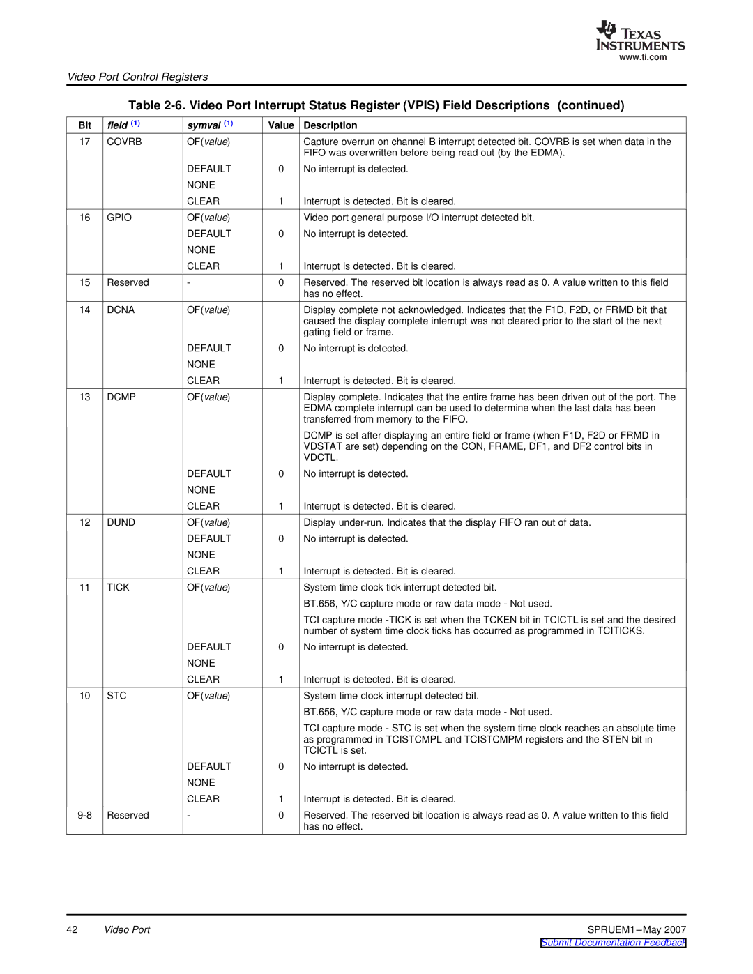
Table
Bit | field (1) | symval (1) | Value | Description |
17 | COVRB | OF(value) |
| Capture overrun on channel B interrupt detected bit. COVRB is set when data in the |
|
|
|
| FIFO was overwritten before being read out (by the EDMA). |
|
| DEFAULT | 0 | No interrupt is detected. |
|
| NONE |
|
|
|
| CLEAR | 1 | Interrupt is detected. Bit is cleared. |
16 | GPIO | OF(value) |
| Video port general purpose I/O interrupt detected bit. |
|
| DEFAULT | 0 | No interrupt is detected. |
|
| NONE |
|
|
|
| CLEAR | 1 | Interrupt is detected. Bit is cleared. |
15 | Reserved | - | 0 | Reserved. The reserved bit location is always read as 0. A value written to this field |
|
|
|
| has no effect. |
14 | DCNA | OF(value) |
| Display complete not acknowledged. Indicates that the F1D, F2D, or FRMD bit that |
|
|
|
| caused the display complete interrupt was not cleared prior to the start of the next |
|
|
|
| gating field or frame. |
|
| DEFAULT | 0 | No interrupt is detected. |
|
| NONE |
|
|
|
| CLEAR | 1 | Interrupt is detected. Bit is cleared. |
13 | DCMP | OF(value) |
| Display complete. Indicates that the entire frame has been driven out of the port. The |
|
|
|
| EDMA complete interrupt can be used to determine when the last data has been |
|
|
|
| transferred from memory to the FIFO. |
|
|
|
| DCMP is set after displaying an entire field or frame (when F1D, F2D or FRMD in |
|
|
|
| VDSTAT are set) depending on the CON, FRAME, DF1, and DF2 control bits in |
|
|
|
| VDCTL. |
|
| DEFAULT | 0 | No interrupt is detected. |
|
| NONE |
|
|
|
| CLEAR | 1 | Interrupt is detected. Bit is cleared. |
12 | DUND | OF(value) |
| Display |
|
| DEFAULT | 0 | No interrupt is detected. |
|
| NONE |
|
|
|
| CLEAR | 1 | Interrupt is detected. Bit is cleared. |
11 | TICK | OF(value) |
| System time clock tick interrupt detected bit. |
|
|
|
| BT.656, Y/C capture mode or raw data mode - Not used. |
|
|
|
| TCI capture mode |
|
|
|
| number of system time clock ticks has occurred as programmed in TCITICKS. |
|
| DEFAULT | 0 | No interrupt is detected. |
|
| NONE |
|
|
|
| CLEAR | 1 | Interrupt is detected. Bit is cleared. |
10 | STC | OF(value) |
| System time clock interrupt detected bit. |
|
|
|
| BT.656, Y/C capture mode or raw data mode - Not used. |
|
|
|
| TCI capture mode - STC is set when the system time clock reaches an absolute time |
|
|
|
| as programmed in TCISTCMPL and TCISTCMPM registers and the STEN bit in |
|
|
|
| TCICTL is set. |
|
| DEFAULT | 0 | No interrupt is detected. |
|
| NONE |
|
|
|
| CLEAR | 1 | Interrupt is detected. Bit is cleared. |
Reserved | - | 0 | Reserved. The reserved bit location is always read as 0. A value written to this field | |
|
|
|
| has no effect. |
42 | Video Port | SPRUEM1 |