www.ti.com
|
|
|
| Display Line Boundary Conditions |
|
|
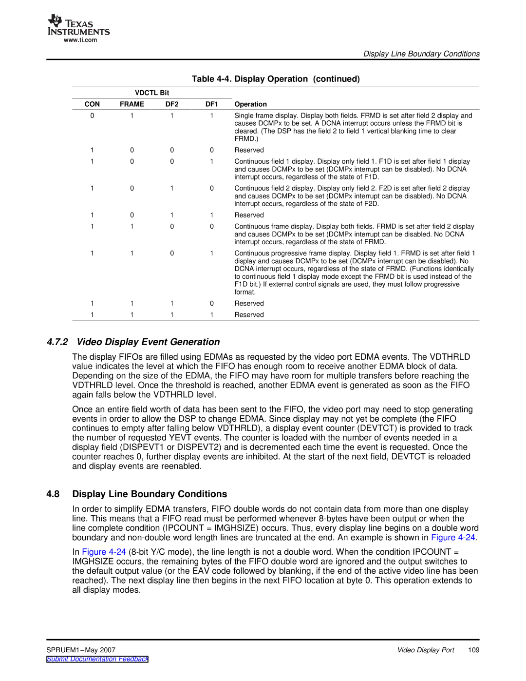
| Table | |
| VDCTL Bit |
|
| |
CON | FRAME | DF2 | DF1 | Operation |
0 | 1 | 1 | 1 | Single frame display. Display both fields. FRMD is set after field 2 display and |
|
|
|
| causes DCMPx to be set. A DCNA interrupt occurs unless the FRMD bit is |
|
|
|
| cleared. (The DSP has the field 2 to field 1 vertical blanking time to clear |
|
|
|
| FRMD.) |
1 | 0 | 0 | 0 | Reserved |
1 | 0 | 0 | 1 | Continuous field 1 display. Display only field 1. F1D is set after field 1 display |
|
|
|
| and causes DCMPx to be set (DCMPx interrupt can be disabled). No DCNA |
|
|
|
| interrupt occurs, regardless of the state of F1D. |
1 | 0 | 1 | 0 | Continuous field 2 display. Display only field 2. F2D is set after field 2 display |
|
|
|
| and causes DCMPx to be set (DCMPx interrupt can be disabled). No DCNA |
|
|
|
| interrupt occurs, regardless of the state of F2D. |
1 | 0 | 1 | 1 | Reserved |
1 | 1 | 0 | 0 | Continuous frame display. Display both fields. FRMD is set after field 2 display |
|
|
|
| and causes DCMPx to be set (DCMPx interrupt can be disabled. No DCNA |
|
|
|
| interrupt occurs, regardless of the state of FRMD. |
1 | 1 | 0 | 1 | Continuous progressive frame display. Display field 1. FRMD is set after field 1 |
|
|
|
| display and causes DCMPx to be set (DCMPx interrupt can be disabled). No |
|
|
|
| DCNA interrupt occurs, regardless of the state of FRMD. (Functions identically |
|
|
|
| to continuous field 1 display mode except the FRMD bit is used instead of the |
|
|
|
| F1D bit.) If external control signals are used, they must follow progressive |
|
|
|
| format. |
1 | 1 | 1 | 0 | Reserved |
1 | 1 | 1 | 1 | Reserved |
4.7.2 Video Display Event Generation
The display FIFOs are filled using EDMAs as requested by the video port EDMA events. The VDTHRLD value indicates the level at which the FIFO has enough room to receive another EDMA block of data. Depending on the size of the EDMA, the FIFO may have room for multiple transfers before reaching the VDTHRLD level. Once the threshold is reached, another EDMA event is generated as soon as the FIFO again falls below the VDTHRLD level.
Once an entire field worth of data has been sent to the FIFO, the video port may need to stop generating events in order to allow the DSP to change EDMA. Since display may not yet be complete (the FIFO continues to empty after falling below VDTHRLD), a display event counter (DEVTCT) is provided to track the number of requested YEVT events. The counter is loaded with the number of events needed in a display field (DISPEVT1 or DISPEVT2) and is decremented each time the event is requested. Once the counter reaches 0, further display events are inhibited. At the start of the next field, DEVTCT is reloaded and display events are reenabled.
4.8Display Line Boundary Conditions
In order to simplify EDMA transfers, FIFO double words do not contain data from more than one display line. This means that a FIFO read must be performed whenever
In Figure
SPRUEM1 | Video Display Port | 109 |
