www.ti.com
Video Capture Registers
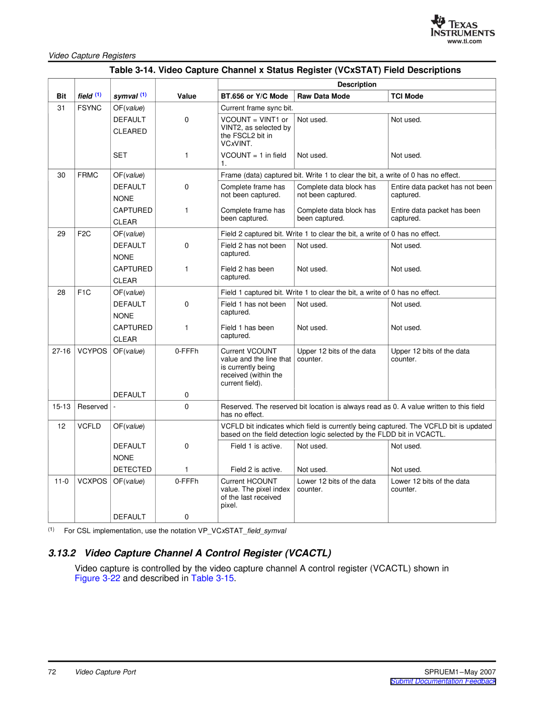
Table
|
|
|
|
| Description |
|
Bit | field (1) | symval (1) | Value | BT.656 or Y/C Mode | Raw Data Mode | TCI Mode |
31 | FSYNC | OF(value) |
| Current frame sync bit. |
|
|
|
| DEFAULT | 0 | VCOUNT = VINT1 or | Not used. | Not used. |
|
| CLEARED |
| VINT2, as selected by |
|
|
|
|
| the FSCL2 bit in |
|
| |
|
|
|
|
|
| |
|
|
|
| VCxVINT. |
|
|
|
| SET | 1 | VCOUNT = 1 in field | Not used. | Not used. |
|
|
|
| 1. |
|
|
30 | FRMC | OF(value) |
| Frame (data) captured bit. Write 1 to clear the bit, a write of 0 has no effect. | ||
|
| DEFAULT | 0 | Complete frame has | Complete data block has | Entire data packet has not been |
|
| NONE |
| not been captured. | not been captured. | captured. |
|
|
|
|
|
| |
|
| CAPTURED | 1 | Complete frame has | Complete data block has | Entire data packet has been |
|
| CLEAR |
| been captured. | been captured. | captured. |
|
|
|
|
|
| |
29 | F2C | OF(value) |
| Field 2 captured bit. Write 1 to clear the bit, a write of 0 has no effect. | ||
|
| DEFAULT | 0 | Field 2 has not been | Not used. | Not used. |
|
| NONE |
| captured. |
|
|
|
|
|
|
|
| |
|
| CAPTURED | 1 | Field 2 has been | Not used. | Not used. |
|
| CLEAR |
| captured. |
|
|
|
|
|
|
|
| |
28 | F1C | OF(value) |
| Field 1 captured bit. Write 1 to clear the bit, a write of 0 has no effect. | ||
|
| DEFAULT | 0 | Field 1 has not been | Not used. | Not used. |
|
| NONE |
| captured. |
|
|
|
|
|
|
|
| |
|
| CAPTURED | 1 | Field 1 has been | Not used. | Not used. |
|
| CLEAR |
| captured. |
|
|
|
|
|
|
|
| |
VCYPOS | OF(value) | Current VCOUNT | Upper 12 bits of the data | Upper 12 bits of the data | ||
|
|
|
| value and the line that | counter. | counter. |
|
|
|
| is currently being |
|
|
|
|
|
| received (within the |
|
|
|
|
|
| current field). |
|
|
|
| DEFAULT | 0 |
|
|
|
Reserved | - | 0 | Reserved. The reserved bit location is always read as 0. A value written to this field | |||
|
|
|
| has no effect. |
|
|
12 | VCFLD | OF(value) |
| VCFLD bit indicates which field is currently being captured. The VCFLD bit is updated | ||
|
|
|
| based on the field detection logic selected by the FLDD bit in VCACTL. | ||
|
| DEFAULT | 0 | Field 1 is active. | Not used. | Not used. |
|
| NONE |
|
|
|
|
|
| DETECTED | 1 | Field 2 is active. | Not used. | Not used. |
VCXPOS | OF(value) | Current HCOUNT | Lower 12 bits of the data | Lower 12 bits of the data | ||
|
|
|
| value. The pixel index | counter. | counter. |
|
|
|
| of the last received |
|
|
|
|
|
| pixel. |
|
|
|
| DEFAULT | 0 |
|
|
|
(1)For CSL implementation, use the notation VP_VCxSTAT_field_symval
3.13.2 Video Capture Channel A Control Register (VCACTL)
Video capture is controlled by the video capture channel A control register (VCACTL) shown in Figure
72 | Video Capture Port | SPRUEM1 |