www.ti.com
Video Display Registers
4.12.12 Video Display Field 2 Image Size Register (VDIMGSZ2)
The video display field 2 image size register (VDIMGSZ2) defines the field 2 image area and specifies the size of the displayed image within the active display.
The image pixel counter (IPCOUNT) counts displayed image pixel output on each of the displayed image. Displayed image pixel output stops when IPCOUNT = IMGHSIZE2. The default output values or blanking values are output for the remainder of the active line.
The image line counter (ILCOUNT) counts displayed image lines. Displayed image output stops when ILCOUNT = IMGVSIZE2. The default output values or blanking values are output for the remainder of the active field.
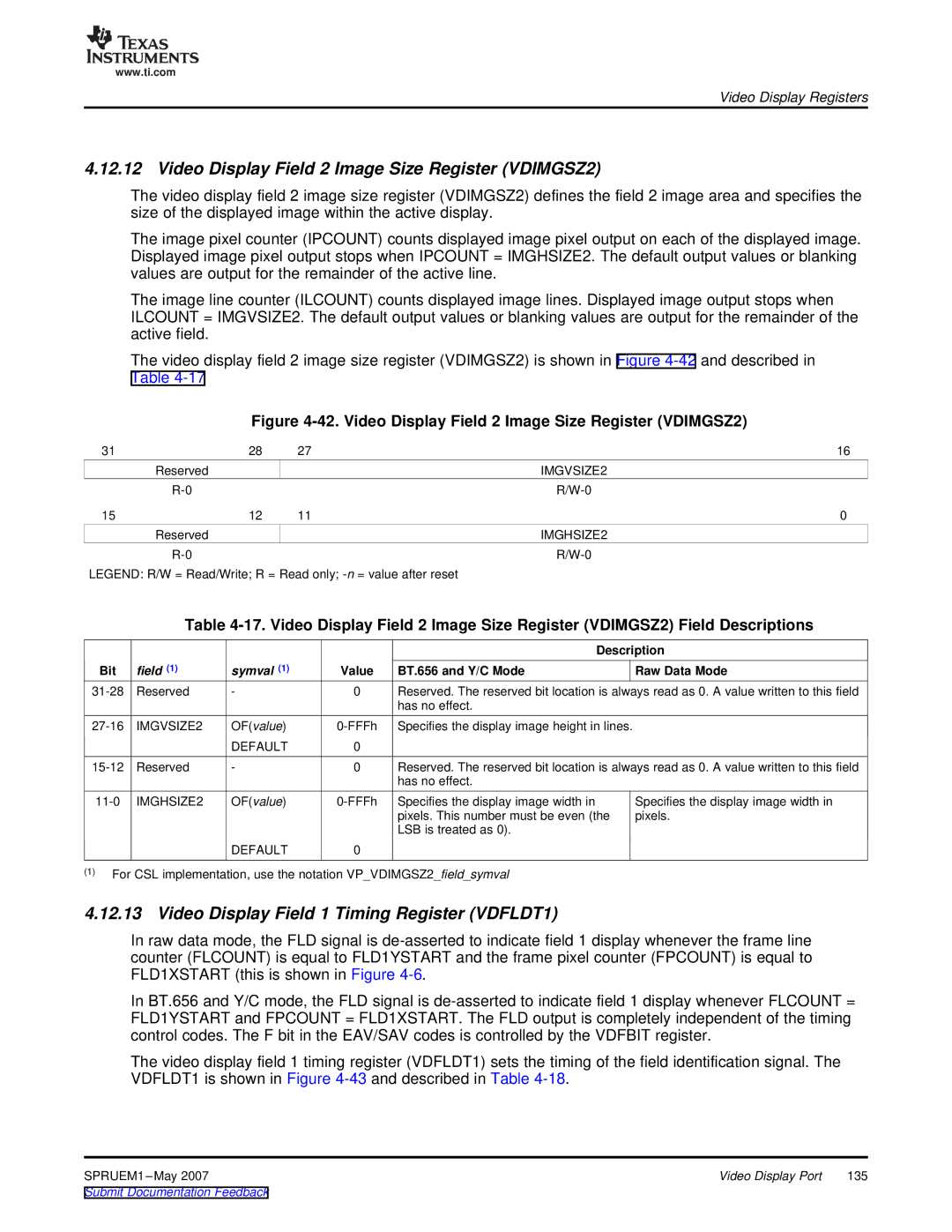
The video display field 2 image size register (VDIMGSZ2) is shown in Figure
Figure 4-42. Video Display Field 2 Image Size Register (VDIMGSZ2)
31 | 28 | 27 | 16 |
| Reserved |
| IMGVSIZE2 |
|
| ||
15 | 12 | 11 | 0 |
| Reserved |
| IMGHSIZE2 |
|
|
LEGEND: R/W = Read/Write; R = Read only;
Table
|
|
|
|
| Description |
Bit | field (1) | symval (1) | Value | BT.656 and Y/C Mode | Raw Data Mode |
Reserved | - | 0 | Reserved. The reserved bit location is always read as 0. A value written to this field | ||
|
|
|
| has no effect. |
|
IMGVSIZE2 | OF(value) | Specifies the display image height in lines. | |||
|
| DEFAULT | 0 |
|
|
Reserved | - | 0 | Reserved. The reserved bit location is always read as 0. A value written to this field | ||
|
|
|
| has no effect. |
|
OF(value) | ||
|
| pixels. This number must be even (the |
|
| LSB is treated as 0). |
| DEFAULT | 0 |
Specifies the display image width in pixels.
(1)For CSL implementation, use the notation VP_VDIMGSZ2_field_symval
4.12.13 Video Display Field 1 Timing Register (VDFLDT1)
In raw data mode, the FLD signal is
In BT.656 and Y/C mode, the FLD signal is
The video display field 1 timing register (VDFLDT1) sets the timing of the field identification signal. The VDFLDT1 is shown in Figure
SPRUEM1 | Video Display Port | 135 |