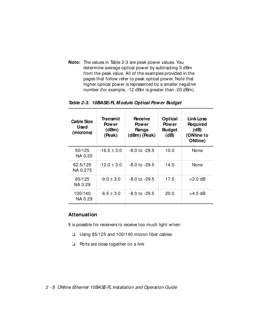
Note: The values in Table
Table 2-3. 10BASE-FL Module Optical Power Budget
Cable Size | Transmit | Receive | Optical | Link Loss | |
Power | Power | Power | Required | ||
Used | |||||
(dBm) | Range | Budget | (dB) | ||
(microns) | |||||
(Peak) | (dBm) (Peak) | (dB) | (ONline to | ||
| |||||
|
|
|
| ONline) | |
|
|
|
|
| |
50/125 | 10.0 | None | |||
NA 0.20 |
|
|
|
| |
|
|
|
|
| |
62.5/125 | 14.5 | None | |||
NA 0.275 |
|
|
|
| |
|
|
|
|
| |
85/125 | 17.5 | >2.0 dB | |||
NA 0.29 |
|
|
|
| |
|
|
|
|
| |
100/140 | 20.0 | >4.5 dB | |||
NA 0.29 |
|
|
|
| |
|
|
|
|
|
Attenuation
It is possible for receivers to receive too much light when:
❑Using 85/125 and 100/140 micron fiber cables
❑Ports are close together on a link
2 - 8 ONline Ethernet