4036-304
MFD Controller Cage
All components within the MFD controller cage are self diagnosed. Any errors are reported as MFD controller cage errors.
Low Voltage Power Supply
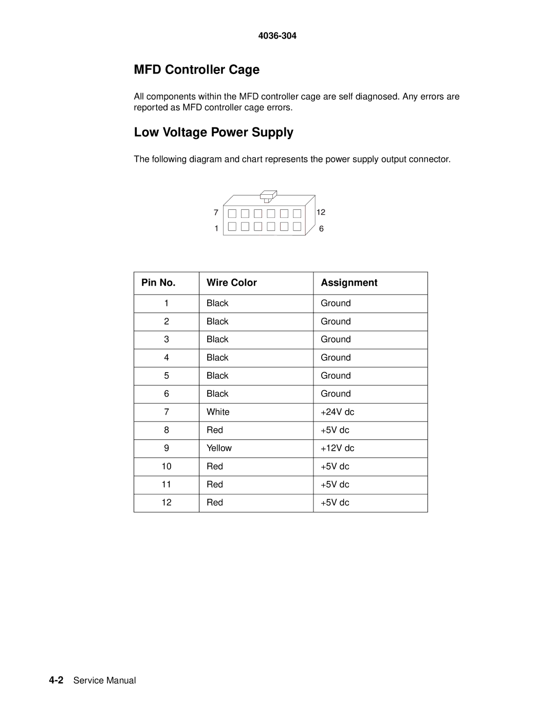
The following diagram and chart represents the power supply output connector.
Pin No. | Wire Color | Assignment |
|
|
|
1 | Black | Ground |
|
|
|
2 | Black | Ground |
|
|
|
3 | Black | Ground |
|
|
|
4 | Black | Ground |
|
|
|
5 | Black | Ground |
|
|
|
6 | Black | Ground |
|
|
|
7 | White | +24V dc |
|
|
|
8 | Red | +5V dc |
|
|
|
9 | Yellow | +12V dc |
|
|
|
10 | Red | +5V dc |
|
|
|
11 | Red | +5V dc |
|
|
|
12 | Red | +5V dc |
|
|
|
