4036-304
4. Connector Locations
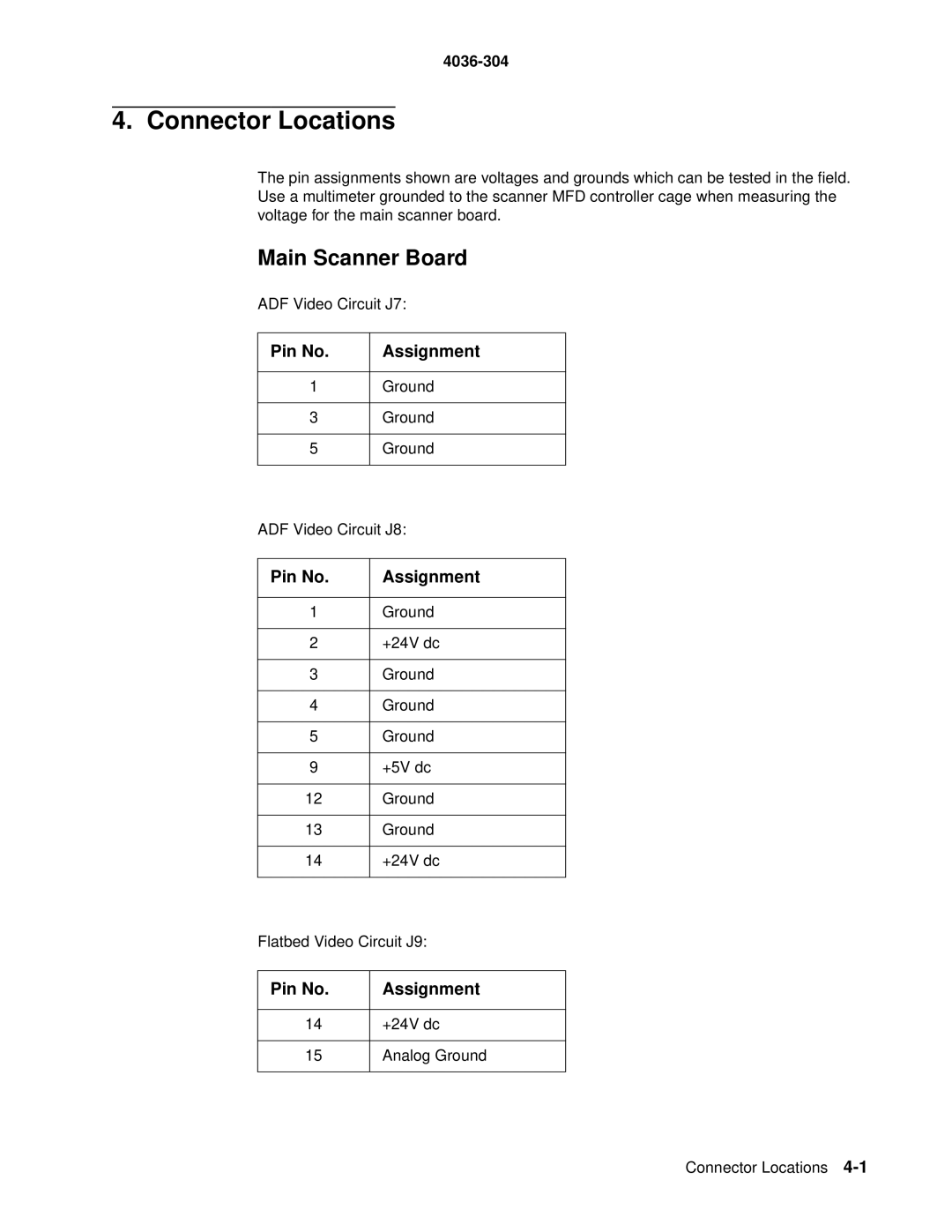
The pin assignments shown are voltages and grounds which can be tested in the field. Use a multimeter grounded to the scanner MFD controller cage when measuring the voltage for the main scanner board.
Main Scanner Board
ADF Video Circuit J7:
Pin No. | Assignment |
|
|
1 | Ground |
3Ground
5Ground
ADF Video Circuit J8:
Pin No. | Assignment |
|
|
1 | Ground |
|
|
2 | +24V dc |
|
|
3 | Ground |
|
|
4 | Ground |
|
|
5 | Ground |
|
|
9 | +5V dc |
|
|
12 | Ground |
|
|
13 | Ground |
|
|
14 | +24V dc |
|
|
Flatbed Video Circuit J9:
Pin No. | Assignment |
14+24V dc
15Analog Ground
Connector Locations
