|
|
|
| |
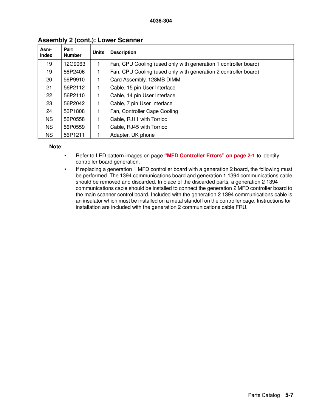
Assembly 2 (cont.): Lower Scanner | ||||
|
|
|
| |
Asm- | Part | Units | Description | |
Index | Number | |||
|
| |||
|
|
|
| |
19 | 12G9063 | 1 | Fan, CPU Cooling (used only with generation 1 controller board) | |
19 | 56P2406 | 1 | Fan, CPU Cooling (used only with generation 2 controller board) | |
20 | 56P9910 | 1 | Card Assembly, 128MB DIMM | |
21 | 56P2112 | 1 | Cable, 15 pin User Interface | |
22 | 56P2110 | 1 | Cable, 14 pin User Interface | |
23 | 56P2042 | 1 | Cable, 7 pin User Interface | |
24 | 56P1808 | 1 | Fan, Controller Cage Cooling | |
NS | 56P0558 | 1 | Cable, RJ11 with Torriod | |
NS | 56P0559 | 1 | Cable, RJ45 with Torriod | |
NS | 56P1211 | 1 | Adapter, UK phone | |
Note:
•Refer to LED pattern images on page “MFD Controller Errors” on page
•If replacing a generation 1 MFD controller board with a generation 2 board, the following must be performed. The 1394 communications board and generation 1 1394 communications cable should be removed and discarded. In place of the discarded parts, a generation 2 1394 communications cable should be installed to connect the generation 2 MFD controller board to the main scanner control board. Included with the generation 2 1394 communications cable is an insulator which must be installed on a metal standoff on the controller cage. Instructions for installation are included with the generation 2 communications cable FRU.
Parts Catalog
