.
|
|
|
| ||
| Concentrator A |
|
|
| |
| 230 m | Unshielded Twisted Pair | 1. | Maximum | 4200 m |
| - |
| Diameter |
| |
|
| A |
|
| |
|
|
|
|
| |
|
| 150 m | 2. |
| 2 m x 560 m |
| |||||
|
| Modules | = 1120 m | ||
|
|
|
| ||
|
| Concentrator B |
| Equivalent Distance | |
|
| 3. |
| 585 m | |
|
|
| Modules |
| |
|
| Unshielded Twisted Pair |
| Equivalent Distance | |
1000 m | 330 m | B | 4. Distances Between | ||
|
| 75 m |
| Transceivers |
|
| 500 m |
| A & B 150 m + 1000 m | ||
|
| 500 m + 75 m | |||
|
|
|
| = 1725 m | |
Concen trat or C
Unshielded Twisted Pair | Remaining | 770 m |
Distance |
C
560 m
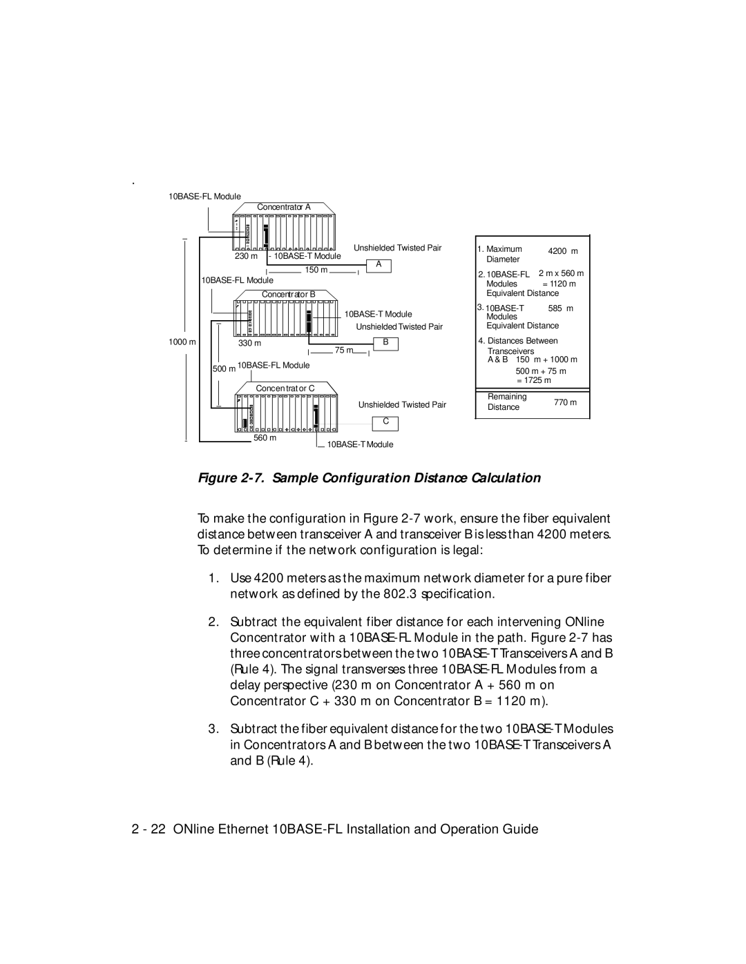
Figure 2-7. Sample Configuration Distance Calculation
To make the configuration in Figure
1.Use 4200 meters as the maximum network diameter for a pure fiber network as defined by the 802.3 specification.
2.Subtract the equivalent fiber distance for each intervening ONline Concentrator with a
3.Subtract the fiber equivalent distance for the two
2 - 22 ONline Ethernet