PREPARATION BEFORE OPERATION
Make the following preparations before operating the power tool:
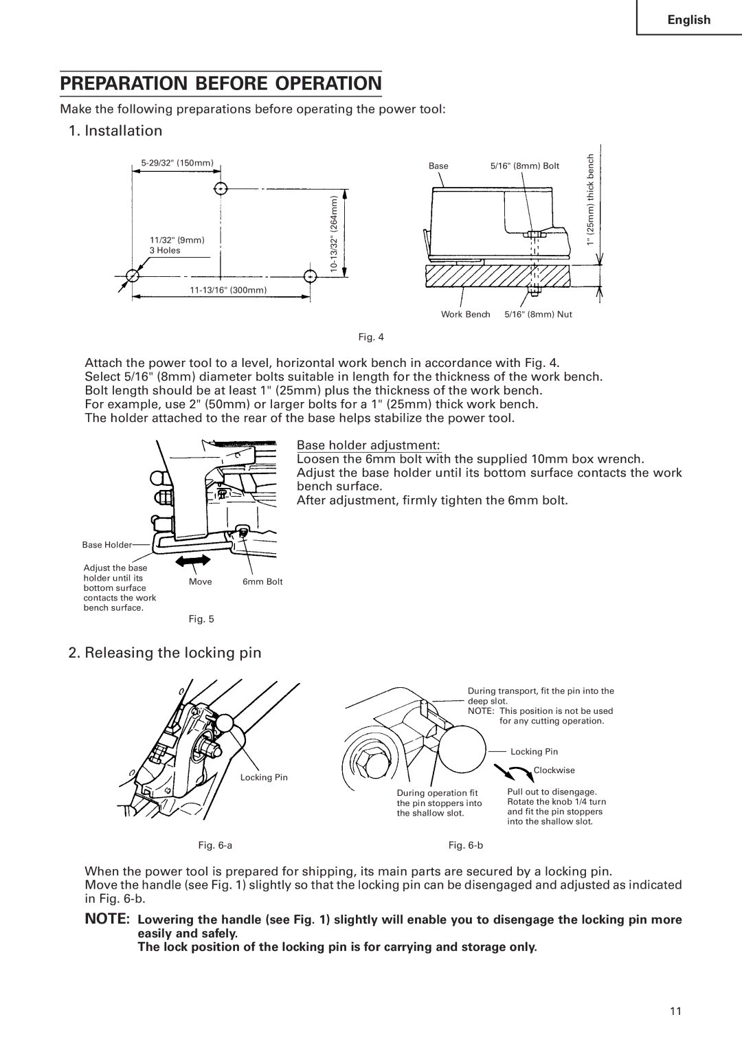
1. Installation
Base | 5/16" (8mm) Bolt | |
| ||
| (264mm) |
|
11/32" (9mm) |
| |
|
|
3 Holes
English
1" (25mm) thick bench
Work Bench 5/16" (8mm) Nut
Fig. 4
Attach the power tool to a level, horizontal work bench in accordance with Fig. 4.
Select 5/16" (8mm) diameter bolts suitable in length for the thickness of the work bench. Bolt length should be at least 1" (25mm) plus the thickness of the work bench.
For example, use 2" (50mm) or larger bolts for a 1" (25mm) thick work bench. The holder attached to the rear of the base helps stabilize the power tool.
Base holder adjustment:
Loosen the 6mm bolt with the supplied 10mm box wrench. Adjust the base holder until its bottom surface contacts the work bench surface.
After adjustment, firmly tighten the 6mm bolt.
Base Holder |
|
| |
Adjust the base |
|
| |
holder until its | Move | 6mm Bolt | |
bottom surface | |||
|
| ||
contacts the work |
|
| |
bench surface. |
|
| |
| Fig. 5 |
|
2. Releasing the locking pin
During transport, fit the pin into the deep slot.
NOTE: This position is not be used for any cutting operation.
Locking Pin
During operation fit the pin stoppers into the shallow slot.
Locking Pin
Clockwise
Pull out to disengage. Rotate the knob 1/4 turn and fit the pin stoppers into the shallow slot.
Fig. | Fig. |
When the power tool is prepared for shipping, its main parts are secured by a locking pin.
Move the handle (see Fig. 1) slightly so that the locking pin can be disengaged and adjusted as indicated in Fig.
NOTE: Lowering the handle (see Fig. 1) slightly will enable you to disengage the locking pin more easily and safely.
The lock position of the locking pin is for carrying and storage only.
11