English
1. Switch operation
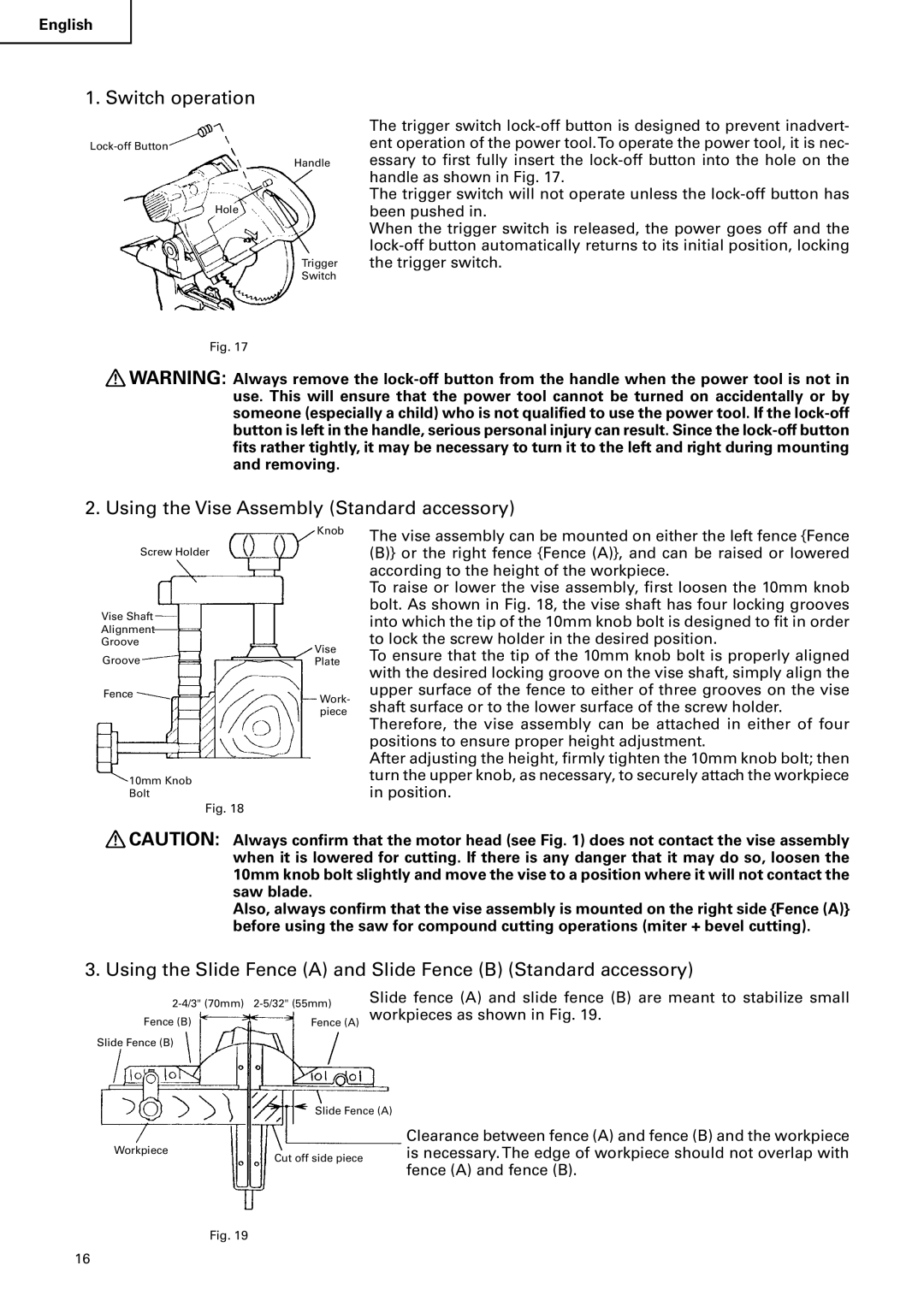
Handle
Hole
Trigger
Switch
Fig. 17
The trigger switch
The trigger switch will not operate unless the
When the trigger switch is released, the power goes off and the
![]() WARNING: Always remove the
WARNING: Always remove the
2. Using the Vise Assembly (Standard accessory)
Knob
Screw Holder
| Vise Shaft |
|
| ||||
|
|
|
|
|
|
| |
| Alignment |
| |||||
| Groove | Vise | |||||
|
|
|
|
|
|
| |
| Groove |
| Plate | ||||
|
|
| |||||
|
| Fence |
| Work- | |||
|
|
|
|
|
|
| |
|
|
|
|
|
|
| piece |
|
| 10mm Knob |
| ||||
|
| Bolt |
| ||||
|
|
|
|
|
|
| Fig. 18 |
The vise assembly can be mounted on either the left fence {Fence (B)} or the right fence {Fence (A)}, and can be raised or lowered according to the height of the workpiece.
To raise or lower the vise assembly, first loosen the 10mm knob bolt. As shown in Fig. 18, the vise shaft has four locking grooves into which the tip of the 10mm knob bolt is designed to fit in order to lock the screw holder in the desired position.
To ensure that the tip of the 10mm knob bolt is properly aligned with the desired locking groove on the vise shaft, simply align the upper surface of the fence to either of three grooves on the vise shaft surface or to the lower surface of the screw holder.
Therefore, the vise assembly can be attached in either of four positions to ensure proper height adjustment.
After adjusting the height, firmly tighten the 10mm knob bolt; then turn the upper knob, as necessary, to securely attach the workpiece in position.
![]() CAUTION: Always confirm that the motor head (see Fig. 1) does not contact the vise assembly when it is lowered for cutting. If there is any danger that it may do so, loosen the 10mm knob bolt slightly and move the vise to a position where it will not contact the saw blade.
CAUTION: Always confirm that the motor head (see Fig. 1) does not contact the vise assembly when it is lowered for cutting. If there is any danger that it may do so, loosen the 10mm knob bolt slightly and move the vise to a position where it will not contact the saw blade.
Also, always confirm that the vise assembly is mounted on the right side {Fence (A)} before using the saw for compound cutting operations (miter + bevel cutting).
3. Using the Slide Fence (A) and Slide Fence (B) (Standard accessory)
Fence (B) | Fence (A) |
Slide Fence (B) |
|
Slide fence (A) and slide fence (B) are meant to stabilize small workpieces as shown in Fig. 19.
Slide Fence (A)
Workpiece
Cut off side piece
Clearance between fence (A) and fence (B) and the workpiece is necessary. The edge of workpiece should not overlap with fence (A) and fence (B).
Fig. 19
16