Control Circuit Terminals
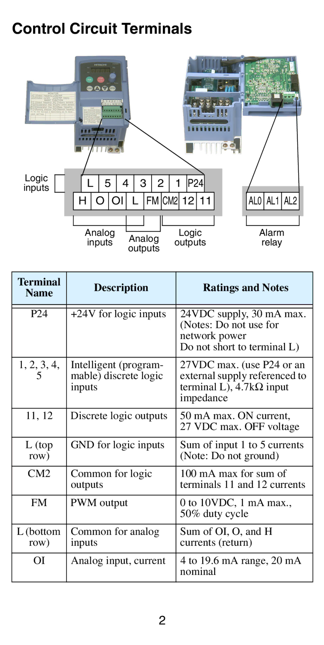
Logic
inputs
L 5 4 3 2 1 P24
H O OI L FM CM2 12 11
|
|
|
|
|
|
| Analog |
|
| Logic |
|
| Analog |
| |||
| inputs | outputs |
| ||
| outputs |
| |||
|
|
|
| ||
AL0 AL1 AL2
Alarm
relay
Terminal | Description | Ratings and Notes | |
Name | |||
|
| ||
|
|
| |
|
|
| |
P24 | +24V for logic inputs | 24VDC supply, 30 mA max. | |
|
| (Notes: Do not use for | |
|
| network power | |
|
| Do not short to terminal L) | |
|
|
| |
1, 2, 3, 4, | Intelligent (program- | 27VDC max. (use P24 or an | |
5 | mable) discrete logic | external supply referenced to | |
| inputs | terminal L), 4.7kΩ input | |
|
| impedance | |
|
|
| |
11, 12 | Discrete logic outputs | 50 mA max. ON current, | |
|
| 27 VDC max. OFF voltage | |
|
|
| |
L (top | GND for logic inputs | Sum of input 1 to 5 currents | |
row) |
| (Note: Do not ground) | |
|
|
| |
CM2 | Common for logic | 100 mA max for sum of | |
| outputs | terminals 11 and 12 currents | |
|
|
| |
FM | PWM output | 0 to 10VDC, 1 mA max., | |
|
| 50% duty cycle | |
|
|
| |
L (bottom | Common for analog | Sum of OI, O, and H | |
row) | inputs | currents (return) | |
|
|
| |
OI | Analog input, current | 4 to 19.6 mA range, 20 mA | |
|
| nominal | |
|
|
|
2