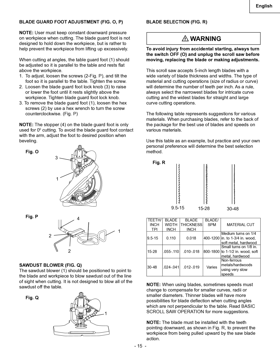
BLADE GUARD FOOT ADJUSTMENT (FIG. O, P)
NOTE: User must keep constant downward pressure on workpiece when cutting. The blade guard foot is not designed to hold down the workpiece, but is rather to help prevent the workpiece from lifting up excessively.
When cutting at angles, the table guard foot (1) should be adjusted so it is parallel to the table and rests flat above the workpiece.
1.To adjust, loosen the screws
2.Loosen the blade guard foot lock knob (3) to raise or lower the foot until it rests slightly above the workpiece. Tighten blade guard foot lock knob.
3.To remove the blade guard foot (1), loosen the hex screws (2) by use a hex wrench to turn the screw counterclockwise. (Fig. P)
NOTE: The stopper (4) on the blade guard foot is only used for 00 cutting. To avoid the blade guard foot contact with the arm, adjust the foot to desired position when beveling.
Fig. O
3 ![]()
![]()
![]()
![]()
![]()
![]()
![]()
1
Fig. P | 4 |
|
English
BLADE SELECTION (FIG. R)
![]() WARNING
WARNING
To avoid injury from accidental starting, always turn the switch OFF (O) and unplug the scroll saw before moving, replacing the blade or making adjustments.
This scroll saw accepts
The following table represents suggestions for various materials. When purchasing blades, refer to the back of the package for the best use of blades and speeds on various materials.
Use this table as an example, but practice and your own personal preference will determine the best selection method.
Fig. R
|
|
| |||
|
|
|
|
|
|
TEETH/ | BLADE |
| BLADE | BLADE/ |
|
INCH | WIDTH | THICKNESS | SPM | MATERIAL CUT | |
2
1
TPI | INCH | INCH |
|
|
|
| Medium turns on 1/4 |
0.110 | 0.018 | ||
|
|
| soft metal, hardwood |
|
|
| Small turns on 1/8 in. |
2
SAWDUST BLOWER (FIG. Q)
The sawdust blower (1) should be positioned to point to the blade and workpiece to blow sawdust out of the line of sight when cutting. It is not designed to blow all of the sawdust off the table.
Fig. Q | I |
| O |
1
|
|
|
| metal, hardwood | |
|
|
|
| ||
Varies | metals/hardwoods | ||||
using very slow | |||||
|
|
|
| ||
|
|
|
| speeds | |
NOTE: When using blades, sometimes speeds must change to compensate for smaller curves, radii or smaller diameters. Thinner blades will have more possibilities for blade deflection when cutting angles which are not perpendicular to the table. Read BASIC SCROLL SAW OPERATION for more suggestions.
NOTE: The blade must be installed with the teeth pointing downward, as shown in Fig. R, to prevent the workpiece from being pulled upward by the saw blade action.
- 15 -