| 2 | . Hardware is common and |
| not available unless listed. | |
|
| |
1 |
| 3 |
4
5
11
![]() 6
6
10
9
8
7
|
|
|
|
|
| 802 |
|
|
|
|
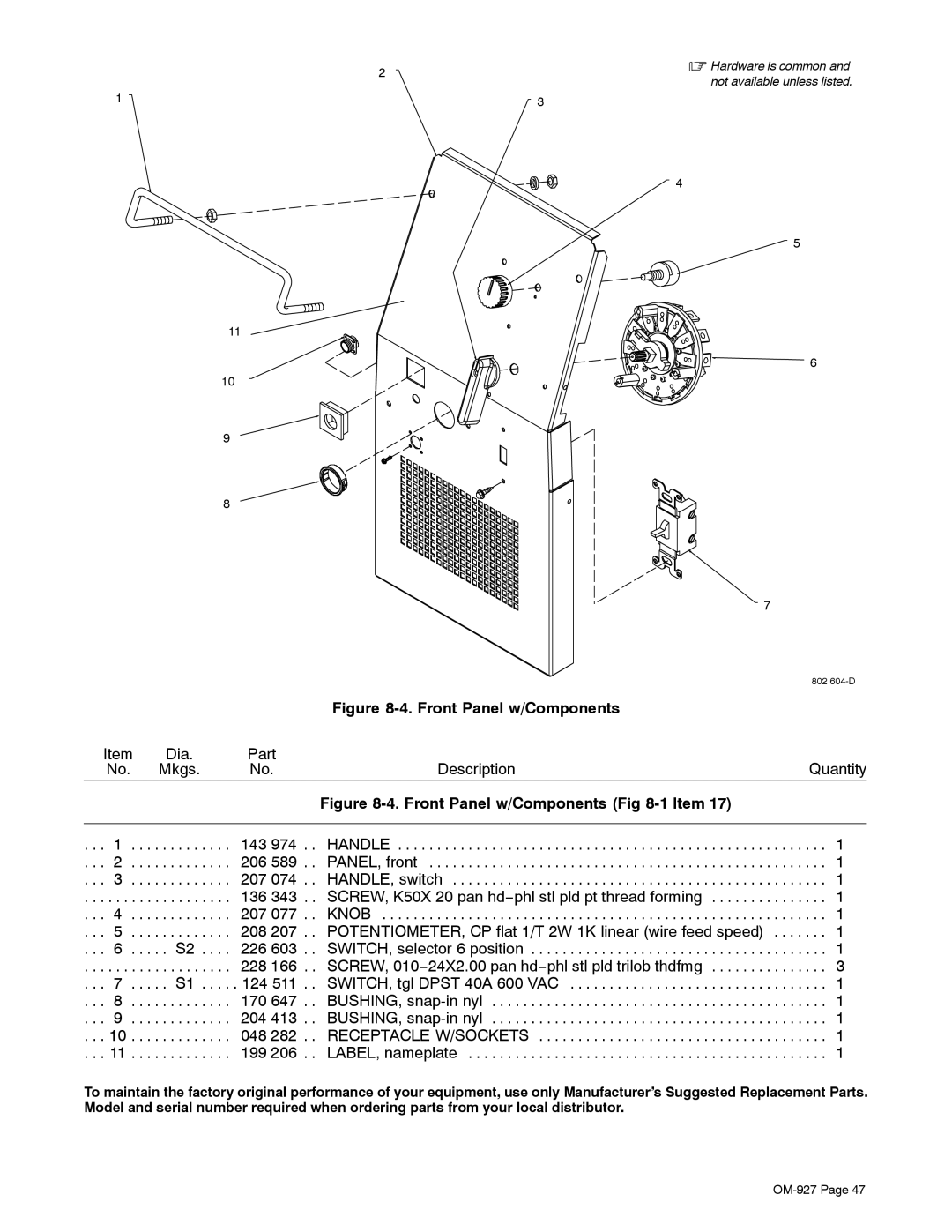
| Figure |
|
Item | Dia. | Part | Description | Quantity | ||
| No. |
| Mkgs. | No. | ||
|
|
|
|
| Figure |
|
|
|
|
|
|
| |
. . . 1 | . . . | . . . . . . . . . . | 143 974 . . | HANDLE | . . . 1 | |
. . . | 2 | . . . | . . . . . . . . . . | 206 589 . . | PANEL, front | . . . 1 |
. . . | 3 | . . . | . . . . . . . . . . | 207 074 . . | HANDLE, switch | . . . 1 |
. . . | . . . | . . . | . . . . . . . . . . | 136 343 . . | SCREW, K50X 20 pan hd−phl stl pld pt thread forming | . . . 1 |
. . . 4 | . . . | . . . . . . . . . . | 207 077 . . | KNOB | . . . 1 | |
. . . | 5 | . . . | . . . . . . . . . . | 208 207 . . | POTENTIOMETER, CP flat 1/T 2W 1K linear (wire feed speed) . . . . | . . . 1 |
. . . | 6 | . . . . . S2 . . . . | 226 603 . . | SWITCH, selector 6 position | . . . 1 | |
. . . | . . . | . . . | . . . . . . . . . . | 228 166 . . | SCREW, 010−24X2.00 pan hd−phl stl pld trilob thdfmg | . . . 3 |
. . . 7 . . . . . S1 | 124 511 . . | SWITCH, tgl DPST 40A 600 VAC | . . . 1 | |||
. . . | 8 | . . . | . . . . . . . . . . | 170 647 . . | BUSHING, | . . . 1 |
. . . | 9 | . . . | . . . . . . . . . . | 204 413 . . | BUSHING, | . . . 1 |
. . . 10 | . . . | . . . . . . . . . . | 048 282 . . | RECEPTACLE W/SOCKETS | . . . 1 | |
. . . 11 | . . . | . . . . . . . . . . | 199 206 . . | LABEL, nameplate | . . . 1 | |
To maintain the factory original performance of your equipment, use only Manufacturer’s Suggested Replacement Parts. Model and serial number required when ordering parts from your local distributor.