Manuals
/
Homelite
/
Lawn and Garden
/
Pressure Washer
Homelite
UT80977 Packing List, Tools Needed, Attaching The Wheel Assembly, Installing The Handle
Models:
UT80546
UT80977
1
12
52
52
Download
52 pages
16.94 Kb
9
10
11
12
13
14
15
16
Troubleshooting
Specification
Install
Symbols
Warranty
Maintenance
Solución De Problemas
Safety
Using The Spray Wand Trigger
Page 12
Image 12
Page 11
Page 13
Page 12
Image 12
Page 11
Page 13
Contents
3000 PSI PRESSURE WASHER
UT80546 / UT80977
SAVE THIS MANUAL FOR FUTURE REFERENCE
MANUEL D’UTILISATION MANUAL DEL OPERADOR
manual
manuel d’utilisation
referencia en el manual del operador
Fig. 1a
B A C D E
A B C
B A C
B A C
A - Water intake rise d’eau, entrada de agua
VIDANGE DE LE LUBRIFIANT CAMBIO DEL LUBRICANTE
TABLE OF CONTENTS
INTRODUCTION
TABLE DES MATIÈRES / ÍNDICE DE CONTENIDO
INTRODUCTION / INTRODUCCIÓN
IMPORTANT SAFETY INSTRUCTIONS
READ ALL INSTRUCTIONS
Page 3 - English
SPECIFIC SAFETY RULES
Page 4 - English
SYMBOLS
DANGER
Page 5 - English
Page 6 - English
ALKALINES, BLEACHES, SOLVENTS, FLAMMABLE MATERIAL
FEATURES
ASSEMBLY
PRODUCT SPECIFICATIONS
ENGINE SWITCH
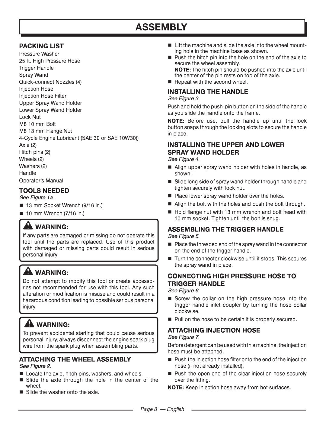
ATTACHING THE WHEEL ASSEMBLY
INSTALLING THE HANDLE
INSTALLING THE UPPER AND LOWER SPRAY WAND HOLDER
CONNECTING HIGH PRESSURE HOSE TO TRIGGER HANDLE
CONNECTING THE HIGH PRESSURE HOSE TO THE PUMP
CONNECTING THE GARDEN HOSE TO THE PRESSURE WASHER
OPERATION
APPLICATIONS
ADDING/CHECKING ENGINE LUBRICANT
OXYGENATED FUELS
ADDING GASOLINE TO THE FUEL TANK
PUMP LUBRICANT
USING THE SPRAY WAND TRIGGER
SELECTING THE RIGHT NOZZLE FOR THE JOB
WASHING WITH DETERGENT
See Figures
MAINTENANCE
GENERAL MAINTENANCE
NOZZLE MAINTENANCE
RINSING WITH THE PRESSURE WASHER
CLEANING/REPLACING THE AIR FILTER
PUMP MAINTENANCE
CHANGING ENGINE LUBRICANT
CHECKING SPARK PLUG
PERIODIC MAINTENANCE SCHEDULE TABLE
PREPARING FOR USE AFTER STORAGE
Page 14 - English
Engine Lubricant
TROUBLESHOOTING
PROBLEM
SOLUTION
CAUSE
WARRANTY
LIMITED NON - ENGINE WARRANTY STATEMENT
Page 16 - English
Page 17 - English
MANUFACTURER’S EMISSION CONTROL SYSTEM WARRANTY COVERAGE
PURCHASER’S/OWNER’S WARRANTY RESPONSIBILITIES
II. EMISSION CONTROL SYSTEM WARRANTY
INSTRUCTIONS IMPORTANTES CONCERNANT LA SÉCURITÉ
AVERTISSEMENT
LIRE TOUTES LES INSTRUCTIONS
Page 3 - Français
RÈGLES DE SÉCURITÉ PARTICULIÈRES
Page 4 - Français
SYMBOLES
SYMBOLE SIGNAL
SIGNIFICATION
Page 5 - Français
AVERTISSEMENT
Page 6 - Français
CARACTÉRISTIQUES
ASSEMBLAGE
FICHE TECHNIQUE
APPRENDRE À CONNAÎTRE LE NETTOYEUR HAUTE PRESSION
INSTALLATION DES ROUES
INSTALLATION DU MANCHE
INSTALLATION DU SUPPORT DE LA LANCE D’ARROSAGE INFÉRIEUR ET SUPÉRIEUR
LISTE DE CONTRÔLE
INSTALLATION DU TUYAU D’INJECTION
UTILISATION
CONNEXION DU FLEXIBLE HAUTE PRESSION SUR LA POMPE
CONNEXION DU TUYAU D’ARROSAGE AU NETTOYEUR HAUTE PRESSION
AJOUT/VÉRIFICATION DE LUBRIFIANT
CARBURANTS OXYGÉNÉS
APPOINT D’ESSENCE
HUILE DE LA POMPE
AVERTISSEMENT
SÉLECTIONNER LA BUSE À RACCORD RAPIDE
APPROPRIÉE POUR LA TÂCHE
NETTOYAGE AVEC DU DÉTERGENT
DÉPLACEMENT DU NETTOYEUR HAUTE PRESSION
ENTRETIEN
RINÇAGE AVEC LE NETTOYEUR HAUTE PRESSION
AVERTISSEMENT
NETOYAGE/ REMPLACEMENT DU FILTRE À AIR
ENTRETIEN DE BUSE
VIDANGE DE LE LUBRIFIANT MOTEUR
ENTRETIEN DE LA BOUGIE
REMISE EN SERVICE APRÈS REMISAGE
TABLEAU DE CALENDRIER D’ENTRETIEN PÉRIODIQUE
Page 14 - Français
DÉPANNAGE
PROBLÈME
Page 15 - Français
GARANTIE
ÉNONCÉ DE LA GARANTIE LIMITÉE HORS MOTEUR
Page 16 - Français
Page 17 - Français
VOS DROITS ET RESPONSABILITÉS EN VERTU DE CETTE GARANTIE
DURÉE DE LA GARANTIE DU FABRICANT SUR LE SYSTÈME ANTIPOLLUTION
II. GARANTIE DU SYSTÈME ANTIPOLLUTION
INSTRUCCIONES IMPORTANTES DE SEGURIDAD
ADVERTENCIA
LEA TODAS LAS INSTRUCCIONES
Página 3 - Español
Página 4 - Español
REGLAS DE SEGURIDAD ESPECÍFICAS
SÍMBOLOS
PELIGRO
PRECAUCIÓN
Página 5 - Español
Página 6 - Español
CARACTERÍSTICAS
ARMADO
ESPECIFICACIONES DEL PRODUCTO
FAMILIARÍCESE CON LA LAVADORA DE PRESIÓN
LISTA DE EMPAQUETADO
HERRAMIENTAS NECESARIAS
MONTAJE DEL CONJUNTO DE LAS RUEDAS
INSTALACIÓN DEL MANGO
FUNCIONAMIENTO
CÓMO CONECTAR LA MANGUERA DE INYECCIÓN
CÓMO CONECTAR LA MANGUERA DE ALTA PRESIÓN A LA BOMBA
CÓMO CONECTAR UNA MANGUERA DE JARDÍN A LA LAVADORA DE PRESIÓN
USOS
ABASTECIMIENTO Y VERIFICACIÓN DE LUBRICANTE
ABASTECIMIENTO DEL TANQUE DE GASOLINA
LUBRICANTE PARA BOMBA
USO DEL MANGO DEL GATILLO
LAVADO CON DETERGENTE
Vea las figuras
Página 11 - Español
MANTENIMIENTO
ENJUAGADO CON LA LAVADORA DE PRESIÓN
TRASLADO DE LA LAVADORA DE PRESIÓN
MANTENIMIENTO GENERAL
MANTENIMIENTO DE LAS BOQUILLAS
LIMPIEZA DEL FILTRO DE AIRE
CAMBIO DEL LUBRICANTE DEL MOTOR
MANTENIMIENTO DE LA BUJÍA
TABLA DEL PROGRAMA PERIÓDICO DE MANTENIMIENTO
PREPARACIÓN DE LA UNIDAD PARA USARLA DESPUÉS DE TENERLA GUARDADA
Página 14 - Español
SOLUCIÓN DE PROBLEMAS
PROBLEMA
CAUSA
SOLUCIÓN
GARANTÍA
DECLARACIÓN DE GARANTÍA LIMITADA NO APLICABLE AL MOTOR
Página 16 - Español
Página 17 - Español
II. GARANTÍA DEL SISTEMA DE CONTROL DE EMISIONES
OPERATOR’S MANUAL
3000 PSI PRESSURE WASHER
UT80546/ UT80977
AVERTISSEMENT
Top
Page
Image
Contents