Attach caster arm (2) to the frame rail as shown with bolt (4) and flange locknut (6). Attach adjustment brackets (3)to frame rail and caster arm
(2)as shown with carnage bolts (5) and flange lock- nuts (6).Repeat for opposite caster. Do not tighten this hardware as the casters will require adjustment when cutting height is set.
Top Link Pivot Installation (figure 4)
Remove bolt (1) and flange locknut (2) from
(2)*3
1. 1/2 X | 083057 A |
|
2.1/2" Flanged hex locknut
3.Top pivot link
Figure 4. A-Frame Installation
Check Chain Installation (figure 5 )
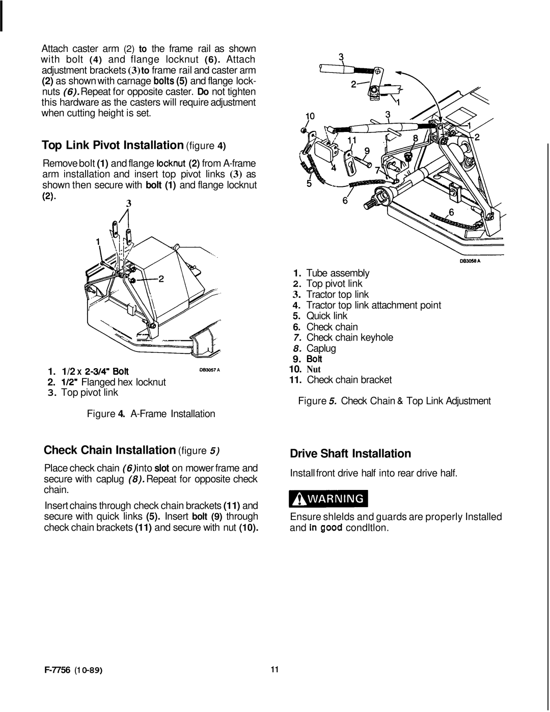
Place check chain (6)into slot on mower frame and secure with caplug (8). Repeat for opposite check chain.
Insert chains through check chain brackets (11) and secure with quick links (5). Insert bolt (9) through check chain brackets (11) and secure with nut (10).
1.Tube assembly
2.Top pivot link
3.Tractor top link
4.Tractor top link attachment point
5.Quick link
6.Check chain
7. Check chain keyhole
8. Caplug
9.BoR
10. Nut
11. Check chain bracket
Figure 5. Check Chain & Top Link Adjustment
Drive Shaft Installation
Install front drive half into rear drive half.
Ensure shlelds and guards are properly Installed and In good condltlon.
11 |
