Lubricate spindle with a medium grade grease. Rotate housing on spindle shaft, checking for free movement.
Blade Spindle Installation
Insert spindle through bottom of mower deck and secure with four mounting bolts. Be sure to position grease fitting toward lubrication access area. Refer to Lubrication in Owner Service section.
Install pulley and key on spindle shaft. Place split taper bushing on pulley and drive down to seat against spindle shaft shoulder and alternately tighten split taper bushing bolts to 12
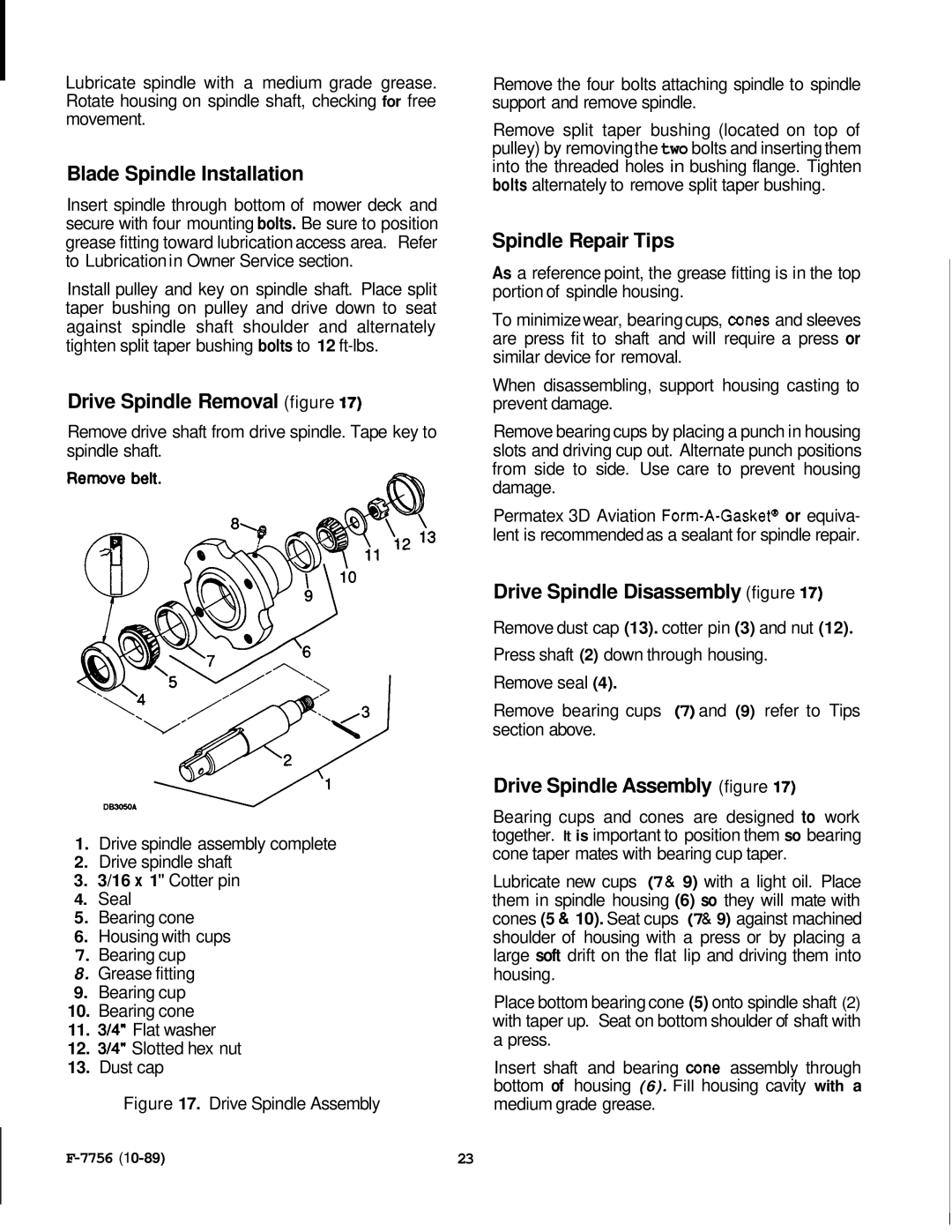
Drive Spindle Removal (figure 17)
Remove drive shaft from drive spindle. Tape key to spindle shaft.
1.Drive spindle assembly complete
2.Drive spindle shaft
3.3/16 x 1" Cotter pin
4.Seal
5.Bearing cone
6.Housing with cups
7.Bearing cup
8. Grease fitting
9.Bearing cup
10. Bearing cone
11. 3/4" Flat washer
12. 3/4" Slotted hex nut
13. Dust cap
Figure 17. Drive Spindle Assembly
Remove the four bolts attaching spindle to spindle support and remove spindle.
Remove split taper bushing (located on top of pulley) by removingthe two bolts and inserting them into the threaded holes in bushing flange. Tighten bolts alternately to remove split taper bushing.
Spindle Repair Tips
As a reference point, the grease fitting is in the top portion of spindle housing.
To minimize wear, bearing cups, cones and sleeves are press fit to shaft and will require a press or similar device for removal.
When disassembling, support housing casting to prevent damage.
Remove bearing cups by placing a punch in housing slots and driving cup out. Alternate punch positions from side to side. Use care to prevent housing damage.
Permatex 3D Aviation
Drive Spindle Disassembly (figure 17)
Remove dust cap (13). cotter pin (3) and nut (12). Press shaft (2) down through housing.
Remove seal (4).
Remove bearing cups (7)and (9) refer to Tips section above.
Drive Spindle Assembly (figure 17)
Bearing cups and cones are designed to work together. It is important to position them so bearing cone taper mates with bearing cup taper.
Lubricate new cups (7& 9) with a light oil. Place them in spindle housing (6) so they will mate with cones (5 & 10). Seat cups (7& 9) against machined shoulder of housing with a press or by placing a large soft drift on the flat lip and driving them into housing.
Place bottom bearing cone (5) onto spindle shaft (2) with taper up. Seat on bottom shoulder of shaft with a press.
Insert shaft and bearing cone assembly through bottom of housing (6). Fill housing cavity with a medium grade grease.
23 |