Place top bearing cone (10) on shaft (2) to mate with top bearing cup (9).
Install washer (11) and nut (12) on shaft (2) and tighten until all bearing free play is removed and there is a slight drag (similar to adjusting the front wheel bearings on an automobile). Check by spinning spindle. It should turn freely.
Be careful not to
Should you
 IMPORTANT NOTICE I
Improper posltlonlng of seals can cause seal fallure.
Proper Seal installation is important. An improperly installed seal will leak and could cause bearing failure. Coat area of housing where seals seat, lightly, with Permatex.
Pull the rubber portion of seal back and locate spring.
Apply a thin coat of lubricant to bottom seal and install with spring up toward center of housing.
Place seal squarely on housing. Select a piece of pipe or tubing with an outside diameter that will set on outside edge of seal. A tube that is too small will bow seal cage.
Carefully press seal into housing, preventing distortionto metal seal cage. Seal should seat firmly and squarely against the machined shoulder in housing.
Make sure seal lip did not roll under. Distortion to seal cage or damage to seal lip will cause seal to leak. Damaged seals must be replaced.
Lubricate spindle with a medium grade grease. Rotate housing on spindle shaft, checking for free movement.
When desired adjustment is obtained, secure nut in position with cotter key and install dust cap (13).
Drive Spindle Installation
Place key in shaft and position pulley on spindle shaft with split taper bushing so the center line of the pulley is
Alternately tighten split taper bushing bolts to secure pulley in proper alignment. Continue alternate tightening sequence until assembly is tight and all bolts are torqued to 12
Check drive pulley and adjust if necessary. When aligned, peen keyway to prevent key from working out.
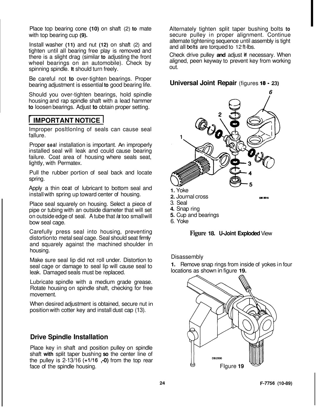
Universal Joint Repair (figures 18 - 23)
6
W
1.Yoke
2.Journal cross | m llll |
3.Seal
4.Snap ring
5.Cup and bearings
6.Yoke
Figure 18. U-Joint Exploded View
Disassembly
1.Remove snap rings from inside of yokes in four locations as shown in figure 19.
Flgure 19
24 |
|