I \
D c 3 w
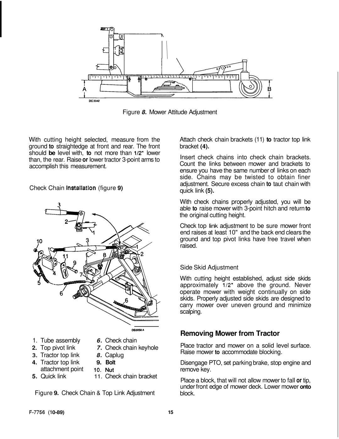
Figure 8. Mower Attitude Adjustment
With cutting height selected, measure from the ground to straightedge at front and rear. The front should be level with, to not more than 1/2" lower than, the rear. Raise or lower tractor 3-point arms to accomplish this measurement.
Check Chain installation (figure 9)
3
\-
1. Tube assembly | 6. Check chain |
2.Top pivot link 7. Check chain keyhole
3. Tractor top link | 8. | Caplug |
4. Tractor top link | 9. | Bolt |
attachment point | 10. | Nut |
5.Quick link11. Check chain bracket Figure 9. Check Chain & Top Link Adjustment
Attach check chain brackets (11) to tractor top link bracket (4).
Insert check chains into check chain brackets. Count the links between mower and brackets to ensure you have the same number of links on each side. Chains may be twisted to obtain finer adjustment. Secure excess chain to taut chain with quick link (5).
With check chains properly adjusted, you will be able to raise mower with
Check top link adjustment to be sure mower front end raises at least 10" and the back end clears the ground and top pivot links have free travel when raised.
Side Skid Adjustment
With cutting height established, adjust side skids approximately 112" above the ground. Never operate mower with weight continually on side skids. Properly adjusted side skids are designed to carry mower over uneven ground and minimize scalping.
Removing Mower from Tractor
Place tractor and mower on a solid level surface. Raise mower to accommodate blocking.
Disengage PTO, set parking brake, stop engine and remove key.
Place a block, that will not allow mower to fall or tip, under front edge of mower deck. Lower mower onto block.
15 |