INSTALLATION SETUP
6.Select the position for the UPS in the equipment rack.
7.Select the proper holes in the rail that position the UPS at the desired location in the rack.
8.With one person lifting each side of the UPS cabinet, carefully slide the UPS into the equipment rack until the
9. Secure the UPS in the rack using eight
Floor Anchor Kit Installation
An optional floor anchor kit
The floor anchor brackets, shipped separately from the UPS and battery cabinet, should be attached inside the lower front and rear edges of the cabinet before installing power and battery modules and before making connections to the intended power source.
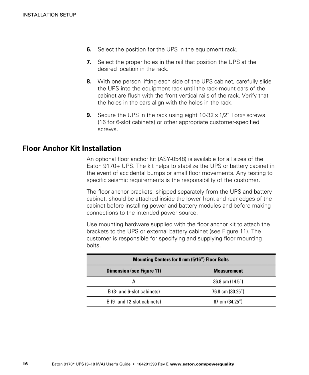
Use mounting hardware supplied with the floor anchor kit to attach the brackets to the UPS or external battery cabinet (see Figure 11). The customer is responsible for specifying and supplying floor mounting bolts.
Mounting Centers for 8 mm (5/16”) Floor Bolts
Dimension (see Figure 11) | Measurement |
|
|
A | 36.8 cm (14.5”) |
|
|
B (3- and | 76.8 cm (30.25”) |
|
|
B (9- and | 87 cm (34.25”) |
|
|
16 | Eaton 9170+ UPS |
