UPS ELECTRICAL INSTALLATION
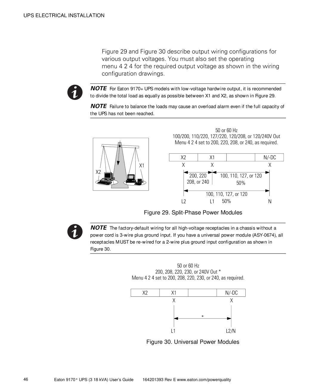
Figure 29 and Figure 30 describe output wiring configurations for various output voltages. You must also set the operating
menu 4 2 4 for the required output voltage as shown in the wiring configuration drawings.
NOTE For Eaton 9170+ UPS models with
NOTE Failure to balance the loads may cause an overload alarm even if the full capacity of the UPS has not been reached.
X1 |
X2 |
50 or 60 Hz
100/200, 110/220, 127/220, 120/208, or 120/240V Out Menu 4 2 4 set to 200, 220, 208, or 240, as required.
X2 |
|
| X1 |
|
|
| ||||||
|
|
|
|
|
|
|
|
|
|
|
|
|
X |
|
| X |
|
|
|
| X | ||||
|
|
|
|
|
|
|
|
|
| |||
|
|
|
|
|
|
|
|
|
| |||
|
| 200, 220 |
|
|
| 100, 110, 127, or 120 |
|
|
| |||
|
| 208, or 240 |
|
| 50% |
|
|
|
| |||
|
|
|
|
|
|
| ||||||
|
|
|
|
|
|
|
| |||||
|
|
| 100, 110, 127, or 120 |
|
|
| ||||||
L2 |
|
| L1 | 50% |
|
| N | |||||
Figure 29. Split-Phase Power Modules
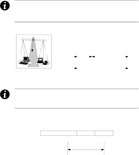
NOTE The
50 or 60 Hz
200, 208, 220, 230, or 240V Out *
Menu 4 2 4 set to 200, 208, 220, 230, or 240, as required.
X2 | X1 |
| X |
X
*
L1L2/N
Figure 30. Universal Power Modules
46 | Eaton 9170+ UPS |