UPS ELECTRICAL INSTALLATION
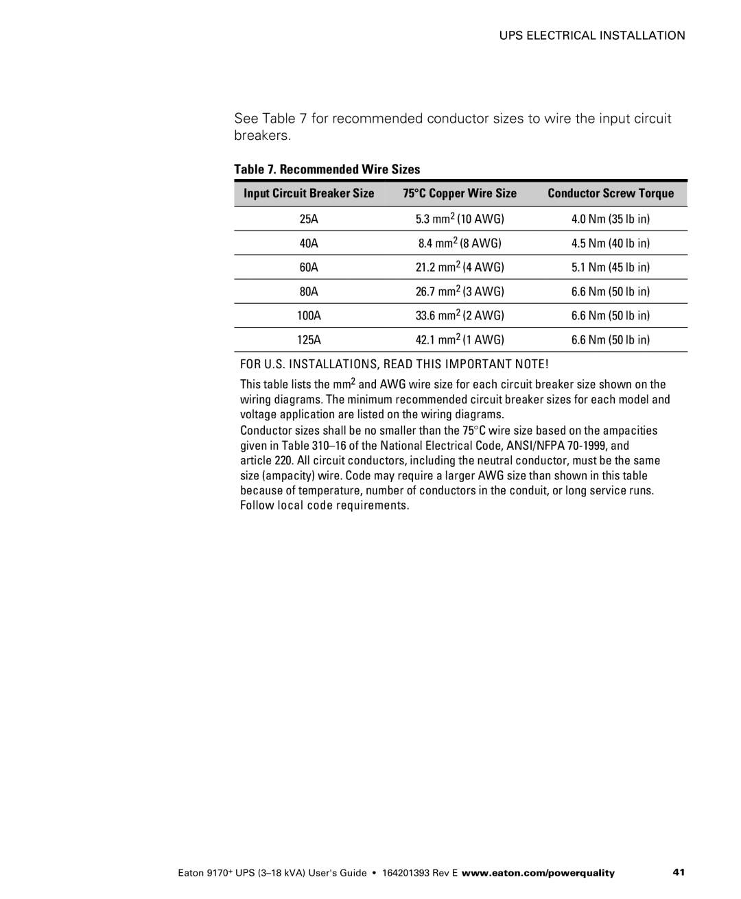
See Table 7 for recommended conductor sizes to wire the input circuit breakers.
Table 7. Recommended Wire Sizes
Input Circuit Breaker Size | 75°C Copper Wire Size | Conductor Screw Torque |
|
|
|
25A | 5.3 mm2 (10 AWG) | 4.0 Nm (35 lb in) |
40A | 8.4 mm2 (8 AWG) | 4.5 Nm (40 lb in) |
60A | 21.2 mm2 (4 AWG) | 5.1 Nm (45 lb in) |
80A | 26.7 mm2 (3 AWG) | 6.6 Nm (50 lb in) |
100A | 33.6 mm2 (2 AWG) | 6.6 Nm (50 lb in) |
125A | 42.1 mm2 (1 AWG) | 6.6 Nm (50 lb in) |
FOR U.S. INSTALLATIONS, READ THIS IMPORTANT NOTE!
This table lists the mm2 and AWG wire size for each circuit breaker size shown on the wiring diagrams. The minimum recommended circuit breaker sizes for each model and voltage application are listed on the wiring diagrams.
Conductor sizes shall be no smaller than the 75°C wire size based on the ampacities given in Table
Eaton 9170+ UPS | 41 |