UPS ELECTRICAL INSTALLATION
3.Install the conduit adapters. AC input and AC output conductors must be run through separate conduits. UPS output circuits must be installed in dedicated conduit systems and not shared with other electrical circuits.
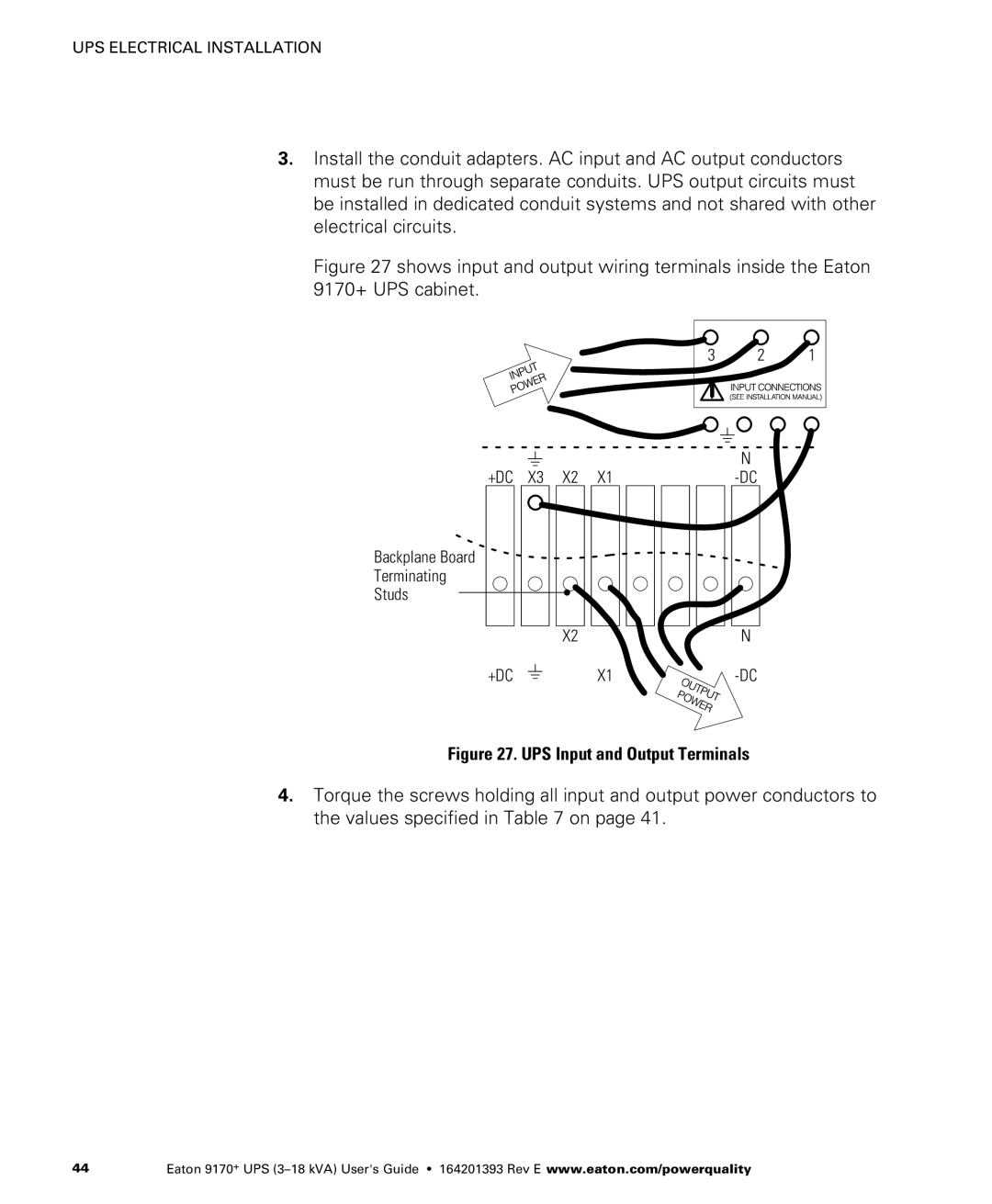
Figure 27 shows input and output wiring terminals inside the Eaton 9170+ UPS cabinet.
3 | 2 | 1 |
|
|
|
| N |
|
|
|
| |
+DC X3 X2 X1 | ||||
Backplane Board
Terminating
Studs
X2N
+DC
X1-DC
Figure 27. UPS Input and Output Terminals
4.Torque the screws holding all input and output power conductors to the values specified in Table 7 on page 41.
44 | Eaton 9170+ UPS |